


49
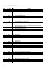
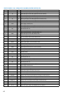
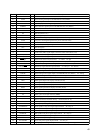
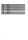
Pin No. Pin Name I/O Description
56
SDATA O
Tuner data output to the FM/AM tuner unit (TM301)
57
SCLK O
Tuner clock signal output to the FM/AM tuner unit (TM301)
58
DATA IN I
PLL data input from the FM/AM tuner unit (TM301)
59
AUSTOP I
Tuned display detection signal input from the FM/AM tuner unit (TM301)
60
STEREO I
Stereo detection signal input from the FM/AM tuner unit (TM301)
61, 62
NC I
Not used (fixed at “L”)
63
VSS —
Ground terminal
64
NC I
Not used (fixed at “L”)
65
TH I
Protect signal input terminal (fixed at “L” in this set)
66
PROTEC I
Over load detect signal input from the protect circuit “L”: protect detect
67
STOP I
AC power check signal input from the power control (IC1206)
68 to 71
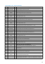
NC I
Not used (fixed at “L”)
72
VIDEO (SW4) O
Video select (SW4) signal output to the video select switch (IC251, 252)
73
X1A —
Not used (open)
74
X0A —
Not used (open)
75
VIDEO (SW3) O
Video select (SW3) signal output to the video select switch (IC251, 252)
76
VIDEO (SW2) O
Video select (SW2) signal output to the video select switch (IC251, 252)
77
VIDEO (SW1) O
Video select (SW1) signal output to the video select switch (IC251, 252)
78
HI-FI/QS I
Model check detection input terminal “L”: HI-FI “H”: QS
79
TAPE NO/YES I
Tape no/yes signal detection input terminal “L”: tape yes “H”: tape no
80
VIDEO 3 NO/YES I
VIDEO 3 no/yes signal detection input terminal “L”: VIDEO 3 yes “H”: VIDEO 3 no
81
DTS NO/YES I
DTS no/yes signal detection input terminal “L”: DTS yes “H”: DTS no
82
ACMUTE O
Muting control signal output to the power amp (IC501, 601, 701)
83
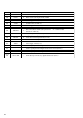
96K NO/YES I
96K no/yes signal detection input terminal Not used
84
TMUTE O
Tuner muting control signal output to the FM/AM tuner unit (TM301) “H”: muting
85
SMUTE O
Surround muting control signal output to the AF amp (IC1508, 1509, 1510)
86
HSTX —
Hardware standby terminal (fixed at “H” in this set)
87
MD2 O
MD2 signal output to the display controller (IC102)
88
MD1 O
MD1 signal output terminal (fixed at “H” in this set)
89 MD0 O
MD0 signal output to the display controller (IC102)
90
REST I
Reset signal input from the display controller (IC102)
91
VSS —
Ground terminal
92
XO O
Main system clock output terminal (16MHz)
93
XI I
Main system clock input terminal (16MHz)
94
VCC —
Power supply terminal (+5V)
95, 96
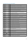
PO0, PO1 I
Rewrite terminal for the flash memory Not used (fixed at “L”)
97
RY-4/8 O
4/8 relay drive signal out put terminal Not used (open)
98
RY-PRE O
Pre amp relay drive signal output terminal “H”: relay on
99
RY-FRONT/A O
Front speaker A relay drive signal output terminal “H”: relay on
100
RY-FRONT/B O
Front speaker B relay drive signal output terminal “H”: relay on
101
RY-CENTER O
Center speaker relay drive signal output terminal “H”: relay on
102
RY-REAR O
Rear speaker relay drive signal output terminal “H”: relay on
103
RY-WOOFER O
Rear woofer relay drive signal output terminal “H”: relay on
104
RY-HP O
Headphone relay drive signal output terminal “H”: relay on
105
RY-POWER O
Power relay drive signal output terminal “H”: relay on
106
ANG/DIG O
Analog/digital select signal output terminal “L”: analog “H”: digital