


53
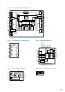
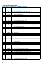
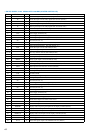
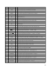
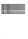
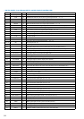
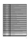
• DIGITAL BOARD IC1503 AK4527 (A/D, D/A CONVERTER)
Pin No. Pin Name I/O Description
1
SDOS I
Data source select terminal “L”: internal ADC output “H”: DAUX input
2 I2C I
Control mode select terminal “L”: 3-wire serial “H”: I2C bus
3 SMUTE I
Soft mute signal input from the system controller (IC1201)
4 BCLK I
Audio serial data clock signal input from the digital audio interface receiver (IC1101)
5 LRCK I
Input channel clock signal input from the digital audio interface receiver (IC1101)
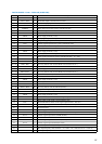
6 SDT1 I
DAC1 audio serial data input from the audio DSP (IC1401)
7 SDT2 I
DAC2 audio serial data input from the audio DSP (IC1401)
8 SDT3 I
DAC3 audio serial data input from the audio DSP (IC1401)
9SDTOO
audio serial data output to the dolby digital audio decoder (IC1301)
10 DAUX I
Audio serial data input terminal Not used (fixed at “L”)
11
DFS I
Double speed sampling mode signal input from the system controller (IC1201)
“L”: normal speed “H”: double speed
12, 13
DEM1, DEM0 I
De-emphasis signal input terminal Not used (fixed at “L”)
14
TVDD —
Power supply terminal (+5V) (for output buffer )
15
D5V —
Power supply terminal (+5V) (digital system)
16
DGND —
Ground terminal (digital system)
17
PD I
Power down and reset signal input terminal “L”: power down and reset
18 ICKS2 I
Clock select 2 input terminal (fixed at “L” in this set)
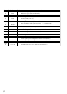
19
ICKS1 I
Clock select 1 input terminal (fixed at “H” in this set)
20
ICKS0 I
Clock select 0 input terminal (fixed at “H” in this set)
21
CAD1 I
Chip address 1 input terminal Used during the serial control mode (fixed at “L” in this set)
22 CAD0 I
Chip address 0 input terminal Used during the serial control mode (fixed at “L” in this set)
23
LOUT3 O
L-ch 3 analog output to the select switch (IC1502)
24
ROUT3 O
R-ch 3 analog output to the select switch (IC1502)
25
LOUT2 O
L-ch 2 analog output to the select switch (IC1502)
26
ROUT2 O
R-ch 2 analog output to the select switch (IC1502)
27
LOUT1 O
L-ch 1 analog output to the select switch (IC1502)
28
ROUT1 O
R-ch 1 analog output to the select switch (IC1502)
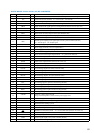
29
LIN– I
L-ch analog negative input from the line amp (IC1504)
30
LIN+ I
L-ch analog positive input from the line amp (IC1504)
31
RIN– I
R-ch analog negative input from the line amp (IC1504)
32
RIN+ I
R-ch analog positive input from the line amp (IC1504)
33
DZF2 O
Zero input detect 2 terminal Not used (open)
34
VCOM O
Common voltage output terminal
Large external capacitor is used to reduce power supply noise
35
VREFH I
Positive voltage reference input terminal (+5V)
36
A5V —
Power supply terminal (+5V) (analog system)
37
AGND —
Ground terminal (analog system)
38
DZF1 O
Zero input detect 1 terminal Not used (open)
39
MCLKI I
Master clock input from the digital audio interface receiver (IC1101)
40
S/P I
Parallel or serial select terminal “L”: serial control mode (fixed at “L” in this set)
41
CS I
Chip select signal input from the system controller (IC1201)
42
CCLK I
Clock signal input from the system controller (IC1201)
43
CDTI I
Control signal output to the system controller (IC1201)
44
LOOP1 O
Loop back mode 1 signal output terminal (fixed at “L” in this set)