


48
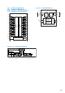
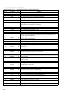
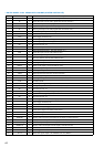
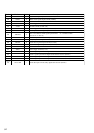
• DIGITAL BOARD IC1201 MB90573PFV-G-296-BND (SYSTEM CONTROLLER)
Pin No. Pin Name I/O Description
1
SCLK O
Serial clock signal output to the dolby digital audio decoder (IC1301)
2SII
Serial data input from the dolby digital audio decoder (IC1301)
3SOO
Serial data output to the dolby digital audio decoder (IC1301)
4CSO
Chip select signal output to the dolby digital audio decoder (IC1301)
5ICO
Reset signal output to the dolby digital audio decoder (IC1301)
6 DSIG I
Data detect signal input from the digital audio interface receiver (IC1101)
7NCO
Not used (fixed at “L”)
8 VCC —
Power supply terminal (+5V)
9 SIN0 I
UART signal input from the display controller (IC102)
10 SOT0 O
UART signal output to the display controller (IC102)
11, 12 NC O
Not used (fixed at “L”)
13 XHDWR O
Data write output to the audio DSP (IC1401)
14 XHDRD O
Data read output terminal Not used (fixed at “L”)
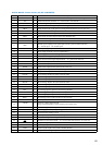
15
SOD I
Serial data input from the audio DSP (IC1401)
16
XHDCS O
Chip select signal output to the audio DSP (IC1401)
17 to 24
HD7 to HD0 O
Two-way data bus with the audio DSP (IC1401)
25 HA0 O
Address data output to the audio DSP (IC1401)
26 XRST O
Reset signal output to the audio DSP (IC1401)
27 HRDY O
Ready signal output to the audio DSP (IC1401)
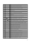
28 CS O
Chip select signal output to the A/D, D/A converter (IC1503)
29
CCLK O
Clock signal output to the A/D, D/A converter (IC1503)
30
CDTI I
Data input from the A/D, D/A converter (IC1503)
31
SMUTE O
Soft mute signal output to the A/D, D/A converter (IC1503)
32
PD O
Reset signal output to the A/D, D/A converter (IC1503)
33
VSS —
Ground terminal
34 C —
External power regulator capacitor is connected terminal
35 96kHz O
Dfs signal output to the A/D, D/A converter (IC1503)
36, 37 NC I
Not used (fixed at “L”)
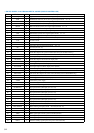
38
DVCC —
Power supply terminal (+5V) (digital system)
39
DVSS —
Ground terminal (digital system)
40, 41
NC O
Not used (fixed at “L”)
42
AVCC —
Power supply terminal (+5V) (analog system)
43
AVR+ —
Power supply terminal (+5V)
44
AVR–—
Ground terminal
45
AVSS —
Ground terminal (analog system)
46
EVSTB O
Serial strobe output to the select switch circuit
47
EVDATA O
Serial data output to the select switch circuit
48
EVCLK O
Serial clock output to the select switch circuit
49
DISPMR I
Display master request signal input from the display controller (IC102)
50
DISPDATA I
Display master data input from the display controller (IC102)
51
SLVDTA/REQ O
Slave data/request output to the display controller (IC102)
52
DISPCLK I
Display master clock input from the display controller (IC102)
53
NC I
Not used (fixed at “L”)
54
VCC —
Power supply terminal (+5V)
55
SLAT O
Tuner latch signal output to the FM/AM tuner unit (TM301)