


3
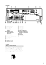
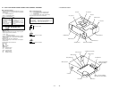
MODEL IDENTIFICATION
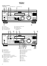
– Rear View –
Part No.
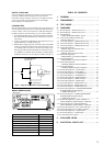
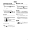
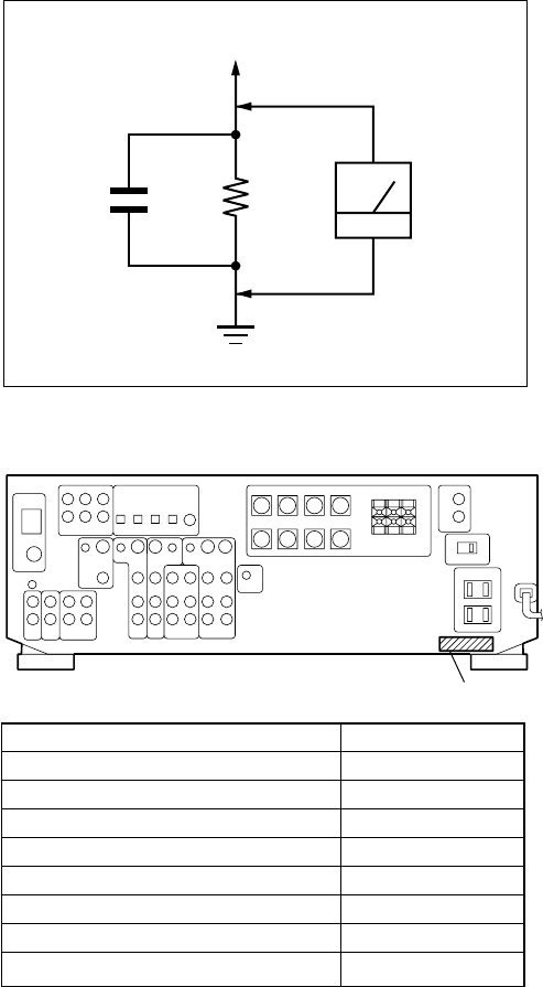
Fig. A. Using an AC voltmeter to check AC leakage.
1.5 k
Ω
0.15 µF
AC
voltmeter
(0.75 V)
To Exposed Metal
Parts on Set
Earth Ground
SAFETY CHECK-OUT
After correcting the original service problem, perform the follow-
ing safety check before releasing the set to the customer:
Check the antenna terminals, metal trim, “metallized” knobs,
screws, and all other exposed metal parts for AC leakage.
Check leakage as described below.
LEAKAGE TEST
The AC leakage from any exposed metal part to earth ground and
from all exposed metal parts to any exposed metal part having a
return to chassis, must not exceed 0.5 mA (500 microamperes.).
Leakage current can be measured by any one of three methods.
1. A commercial leakage tester, such as the Simpson 229 or RCA
WT-540A. Follow the manufacturers’ instructions to use these
instruments.
2. A battery-operated AC milliammeter. The Data Precision 245
digital multimeter is suitable for this job.
3. Measuring the voltage drop across a resistor by means of a VOM
or battery-operated AC voltmeter. The “limit” indication is 0.75
V, so analog meters must have an accurate low-voltage scale.
The Simpson 250 and Sanwa SH-63Trd are examples of a pas-
sive VOM that is suitable. Nearly all battery operated digital
multimeters that have a 2 V AC range are suitable. (See Fig. A)
TABLE OF CONTENTS
1. GENERAL ................................................................... 4
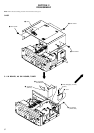
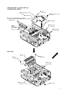
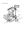
2. DISASSEMBLY ......................................................... 6
3. TEST MODE .............................................................. 9
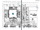
4. DIAGRAMS
4-1. Block Diagram – MAIN Section (1/2) – ........................ 11
4-2. Block Diagram – MAIN Section (2/2) – ........................ 12
4-3. Block Diagram
– DISPLAY/POWER SUPPLY Section – ...................... 13
4-4. Note for Printed Wiring Boards and
Schematic Diagrams ...................................................... 14
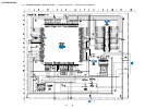
4-5. Schematic Diagram – DIGITAL Board (1/3) – .............. 15
4-6. Schematic Diagram – DIGITAL Board (2/3) – .............. 16
4-7. Schematic Diagram – DIGITAL Board (3/3) – .............. 17
4-8. Printed Wiring Board
–DIGITAL Board (Component Side) ............................. 18
4-9. Printed Wiring Board
–DIGITAL Board (Conductor Side) ............................... 19
4-10. Printed Wiring Boards
–VIDEO/JOINT (1) (H) Boards (DE845) – ................... 20
4-11. Schematic Diagram
–VIDEO/JOINT (1) (H) Boards (DE845) – ................... 21
4-12. Printed Wiring Boards
– OSD/OSD JOINT (H) Boards (DE945) – ................... 22
4-13. Schematic Diagram
– OSD/OSD JOINT (H) Boards (DE945) – ................... 23
4-14. Printed Wiring Board – AU SW Board – ....................... 24
4-15. Schematic Diagram – AU SW Board – .......................... 25
4-16. Printed Wiring Board – S-VIDEO Board – .................... 26
4-17. Schematic Diagram – S-VIDEO Board –....................... 27
4-18. Printed Wiring Board –DISPLAY Board – .................... 28
4-19. Schematic Diagram – DISPLAY Board – ...................... 29
4-20. Printed Wiring Board – MAIN Board – ......................... 30
4-21. Schematic Diagram – MAIN Board (1/3) – ................... 31
4-22. Schematic Diagram – MAIN Board (2/3) – ................... 32
4-23. Schematic Diagram – MAIN Board (3/3) – ................... 33
4-24. Printed Wiring Boards – H.P/MUTING/POWER/
ROTARY/VIDEO 3(DE945)/VOL/
V. SWITCH (E) Boards – ............................................... 34
4-25. Schematic Diagram – H.P/MUTING/POWER/
ROTARY/VIDEO 3(DE945)/VOL/
V. SWITCH (E) Boards – ............................................... 35
4-26. Printed Wiring Boards – BIAS (C)/BIAS (L)
/BIAS (R)/BIAS (LS)/BIAS (RS)/5.1 IN Boards – ....... 36
4-27. Schematic Diagram – BIAS (C)/BIAS (L)
/BIAS (R)/BIAS (LS)/BIAS (RS)/5.1 IN Boards – ....... 37
4-28. Printed Wiring Boards –DC (1)/DC (2) Boards – .......... 38
4-29. Schematic Diagram –DC (1)/DC (2) Boards – .............. 39
4-30. Printed Wiring Boards –AC/SP Boards –....................... 40
4-31. Schematic Diagram – AC/SP Boards – .......................... 41
4-32. IC Pin Function Description ........................................... 46
5. EXPLODED VIEWS ................................................ 56
6. ELECTRICAL PARTS LIST ............................... 59
Model
DE945: US model
DE945: Canadian model
DE845: US model
DE845: Canadian model
Malaysia and Singapore models
Chinese model
Australian model
E and PX models
Part No.
4-226-871-0s
4-226-871-1s
4-226-871-3s
4-226-871-4s
4-226-871-5s
4-226-871-6s
4-226-871-7s
4-226-871-8s