


– 38 –
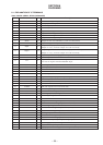
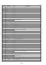
Pin No. Pin name I/O Description
51 AVREF I A/D converter reference voltage input.
52 AVDD – A/D converter power supply terminal.
53 AM3 MNT I AC adaptor or EXT battery detection input. L : EXT battery
54 TEMP I Temp meter (IC803) input.
55 KEY3 I PLAY/REC key input.
56 KEY4 I Key input.
57 KEY0 I Key input.
58 KEY1 I Key input.
59 UNREG MNT I UNREG voltage monitor.
60 LIP MNT I Voltage monitor for lithium battery.
61 FG IN I FG input from motor driver (IC701).
62 SLA I
63 SLB I
JOG dial signal input.
64 INT SW I INITIAL switch input.
65 PACK IN I MEDIA switch input.
66 JACKDET I Input jack detection input.
67 OPT DET I Detecting input an optical input.
68 MIC DET I MIC jack detection.
69 XLAT O Latch output.
70 KEY ON O TRACK MARK jack input.
71 ST1 A O
72 ST2 A O
Stepping motor control signal output.
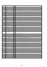
73 –––– – Not used (Open).
74 –––– – Not used (Open).
75 DQSY I Subcode Q sync (SCOR) of digital in U-bit CD format from IC503.
76 T COUNT I Traverse count signal input.
77 SDI1 I Serial data input.
78 SDO1 O Serial data output.
79 SCK1 O Serial clock output.
80 SQSY I SUB-Q/ADIP SYNC input.
81 BEEP O BEEP sound output control. H : BEEP sound output
82 XLIP DET I This is at “L” level when using the lithium battery or with no sensor switch input.
83 REFLCT I CD/MO discrimination switch.
84 TEX – Not used (Fixed at “L”)
85 XT – Not used (Open).
86 VSS – Ground.
87 VDD – Power supply pin (+2.8V).
88 NC – Not used (Fixed at “H”)
89 XCS ADA I Chip select input.
90 XPD ADA O D/A converter power down detect during recording. H : Power down
91 ST1B O
92 ST2B O
Stepping motor control signal output.
93 A MUTE O Analog mute control. L : Mute
94 OPT CONT O Power supply control output for an optical input.
95 CS EVR O
96 CS NV O
Chip select output.
97 SCK2 O Serial clock output.
98 ––––––– O HF module control output. (Not used : open)
99 SDO2 O Serial data output.
100 XLIP O Charge control. H : Charge