


– 33 –
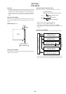
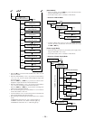
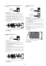
5-7. Low Reflection CD Traverse Adjustment
Connection :
Adjusting Method :
1. Set the servo mode of the test mode (Mode : 000).
2. Press the ” key, and set the low reflection CD playback adjust-
ment mode (Mode : 040) using the volume + and – keys.
3. Load any MO disc available on the market.
4. When the ” key is pressed, the low reflection CD playback EF
balance adjustment mode (Mode : 042) will be set after low re-
flection CD focus search ON (Mode : 041).
5. Press the P key to perform automatic adjustment, and check
that the traverse waveform is symmetrical at the top and bottom.
6. Check that the traverse level at this time is above 0.9Vp-p.
7. Press the p key.
8. Exit the test mode.
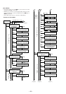
5-8. CD Traverse Adjustment
Connection :
Adjusting Method :
1. Set the servo mode of the test mode (Mode : 000).
2. Press the ” key, and set the CD playback adjustment mode (Mode
: 050) using the volume + and – keys.
3. Press the = and + keys and move the optical pickup to the
center circumference.
4. Load a CD test disc (TDYS-1).
5. When the ” key is pressed, the CD playback EF balance adjust-
ment mode (Mode : 052) will be set after CD focus search ON
(Mode : 051).
6. Press the P key to perform automatic adjustment, and check
that the traverse waveform is symmetrical at the top and bottom.
7. Check that the traverse level at this time is above 1.0Vp-p.
8. Press the p key.
9. Exit the test mode.
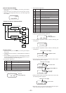
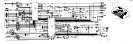
Oscilloscope
MAIN board
TP5980 (TE)
AP5430 (VC)
(Traverse Waveform)
A
B
C
Specification : A = B, C 0.9Vp-p
0V
>
=
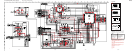
Oscilloscop
e
MAIN board
TP5980 (TE)
AP5430 (VC)
(Traverse Waveform)
A
B
C
Specification : A = B, C 1.0 Vp-p
0V
>
=
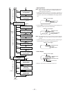
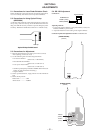
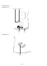
5-9. CD RF Level Check
Connection :
Adjusting Method :
1. Set the servo mode of the test mode (Mode : 000).
2. Press the ” key, and set the CD playback adjustment mode (Mode
: 050) using the volume + and -keys.
3. Press the = and + keys and move the optical pickup to the
center circumference.
4. Load a CD test disc (TDYS-1).
5. When the ” key is pressed, the CD EF balance adjustment mode
(Mode : 052) will be set after CD focus search ON (Mode :
051).
6. When the ” key is pressed, the ABCD level adjustment mode
(Mode : 053) is set.
7. Press the P key to perform automatic adjustment, and check
that the RF level is 1.1 ±0.3Vp-p.
8. Check that the voltage between AP574 (LDIO) and AP5117
(VCC) and at this time is below 40mV.
9. Press the p key.
10.Exit the test mode.
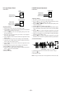
Digital voltmete
r
MAIN board
AP5117 (VCC)
AP574 (LDIO)
Oscilloscope
MAIN board
AP5500 (RF)
AP5430 (VC)
1.1 – 0.3 Vp-p
(RF waveform)