


– 25 –
SECTION 4
TEST MODE
[Operations When Test Mode is Set]
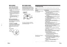
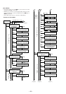
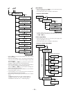
When the test mode is set, the LCD will display as follows.
• The LCD performs the following repeatedly.
ROM version displayed / all lit / all off
• The display can be held and checked by pressing P key.
• The self-diagnostic display appears while the DISPLAY key is
pressed.
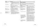
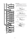
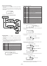
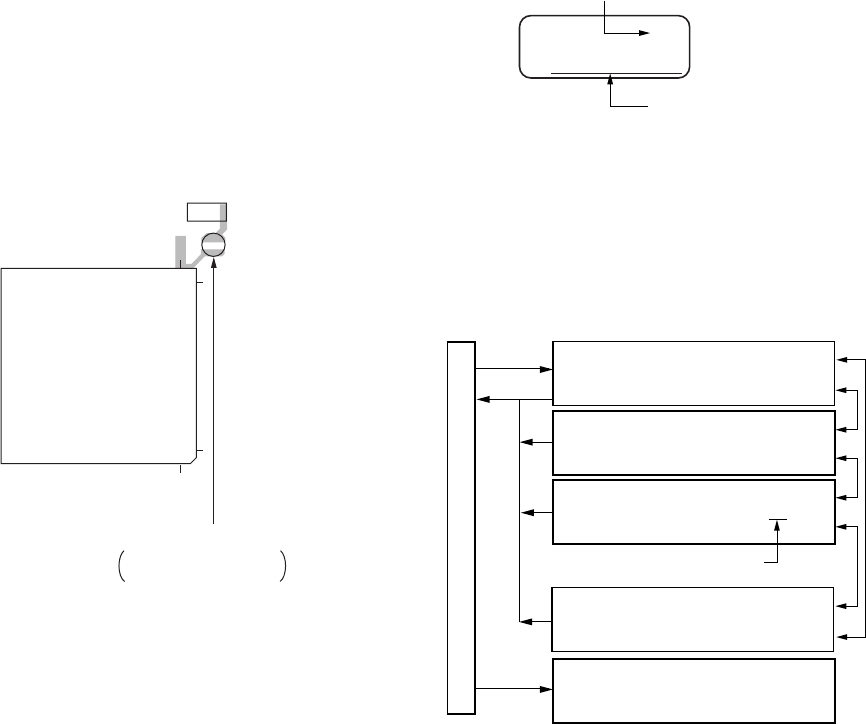
[Structure of Test Mode]
The test mode of this unit consists of the following five modes.
• In modes other than the general adjustment mode, the last two
digits of the mode number will be displayed at the 00 section.
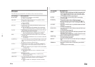
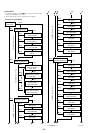
[Outline]
• The general adjustment mode of this unit performs CD and MO
adjustments automatically when set. In this mode, the disc is de-
termined if CD or MO and adjustments are automatically per-
formed in order. If errors are detected , the faulty locations are
displayed. The servo mode performs each adjustment automati-
cally.
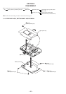
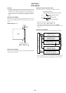
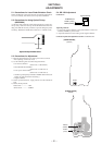
[Setting the Test Mode]
Short-circuit the soldering bridge of TAP803 (TEST) on the main
board (connect Pin @§ of IC801 to the GND) and turn on the power
supply.
[MAIN BOARD] (SIDE B)
[Exiting the Test Mode]
Turn off the power supply and open the soldering bridge of TAP803
(TEST) on the main board.
25
100
26
1
IC801
C315
TAP803
(TEST)
TAP803 (Test mode)
Short : Test mode
Open : Normal mode
Self-diagnostic display
(displayed while the DISPLAY key is pressed)
Segment section
Dot section
ROM version displayed
00
Ver 01.00
p key
+ key
VOLUME +key or – key
Display when Test Mode is Set
= key
Servo Mode
Segment Section : 00
Dot Section : SERVO
Audio Mode
Segment Section : 00
Dot Section : AUDIO
Power Mode
Segment Section : 00
Dot Section : POWER
General Adjustment Mode
Segment Section : 4000
Dot Section : Assy MODE
Mecha Mode
Segment Section : 00 00
Dot Section : MECHA
Select dial number (blinks)