


– 31 –
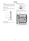
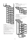
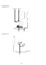
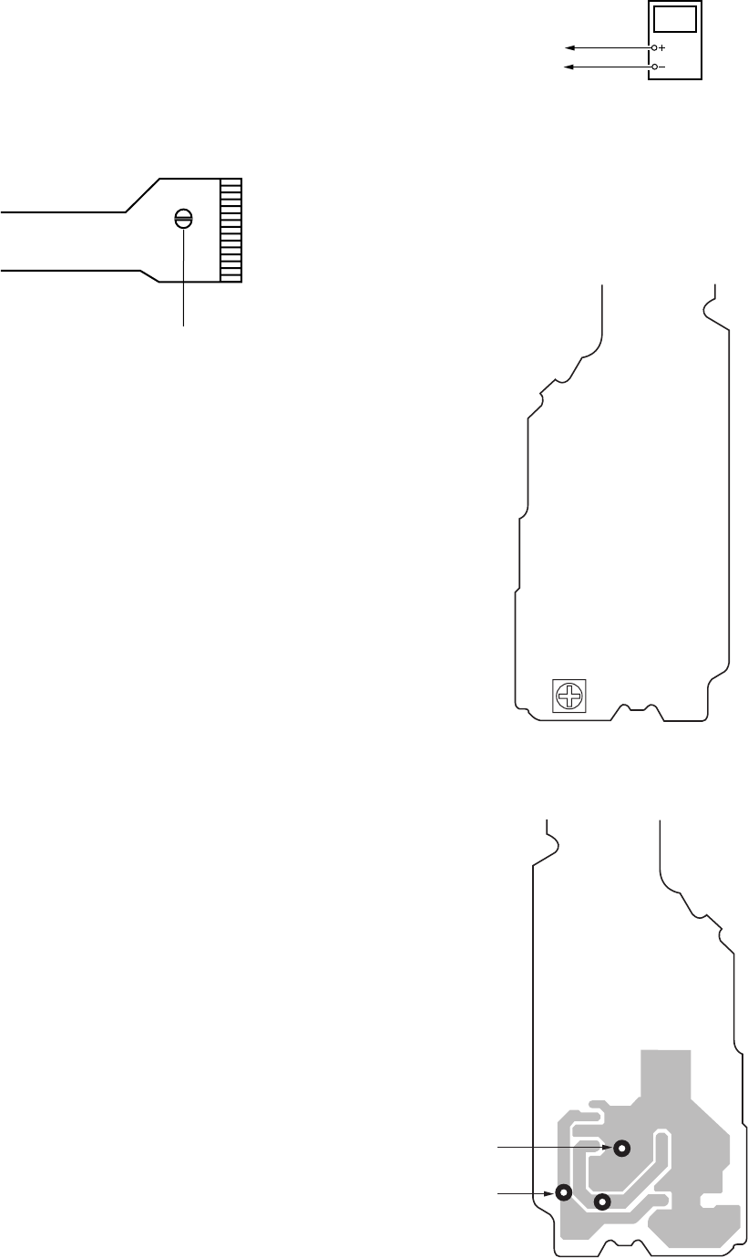
5-4. DD 2.8V Adjustment
Connection :
Adjusting Method :
1. Connect the digital voltmeter to test point TP8507 (+2.8V) and
TP8505 (AGND) on power board.
2. Adjust the RV801 for 2.8V reading on the digital voltmeter.
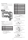
Connection point and adjustment location : POWER board
SECTION 5
ADJUSTMENTS
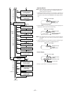
5-1. Precautions for Laser Diode Emission Check
When checking the emission of the laser diode during adjustments,
never view directly downwards as this may lead to blindness.
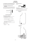
5-2. Precautions for Using Optical Pickup
(KMS-280A)
As the laser diode inside the optical pickup damages by static elec-
tricity easily, solder the laser tap of the flexible board when han-
dling. Also take the necessary measures to prevent damages by static
electricity. Handle the flexible board with care as it breaks easily
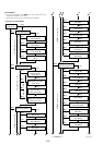
5-3. Precautions for Adjustment
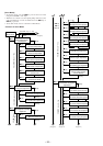
1) Perform all adjustments in the order given in the test mode.
After adjusting, exit the test mode.
2) Use the following tools and measuring instruments.
• CD test disc TDYS-1
(Parts Code : 4-963-646-01)
• Recorded MO disc PTDM-1
(Parts Code : J-2501-054-A)
• Laser power meter LPM-1
(Parts Code : J-2501-046-A)
• Oscilloscope (Frequency band above 40MHz. Perform the cali-
bration of probe first before measuring.)
• Digital voltmeter
3) Unless specified othewise, supply DC 6V from the DC IN 6V
jack.
4) Swtich, knob positions
Hold switch
• • • • • • • • • • • • • • • • OFF
AVLS switch • • • • • • • • • • • • • • NORM
Laser tap
Optical Pickup flexible board
Digital voltmete
r
POWER board
TP8507 (+2.8V)
TP8505 (AGND)
TP8505
TP8503
TP8507
RV801
[POWER BOARD]
(SIDE A)
[POWER BOARD]
(SIDE B)
TP8505
(AGND)
TP8507
(+2.8V)