


– 2 –
Specifications ........................................................................... 1
1. SERVICING NOTE ....................................................... 3
2. GENERAL
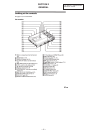
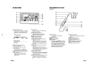
Location and Function of Controls .................................... 4
3. DISASSEMBLY
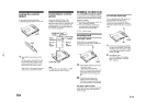
3-1. Upper Panel Assy, Bottom Panel Assy Removal ...... 20
3-2. Main Board Removal ............................................... 21
3-3. Mechanism Deck (MT-MZR50-143) Removal ........ 21
3-4. Optical Pick-up Assy, REC Board Removal ............ 22
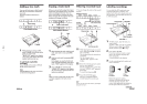
3-5. CLV Board Removal ................................................ 22
3-6. Battery Case Assy Removal ..................................... 23
3-7. Power Board, Switch Board Removal ...................... 23
3-8. Switch Unit (with JOG Dial) Removal .................... 24
4. TEST MODE................................................................. 25
5. ADJUSTMENTS ......................................................... 31
6. DIAGRAMS
6-1. Explanation of IC Terminals..................................... 35
6-2. Block Diagrams ........................................................ 39
6-3. Circuit Boards Location ........................................... 43
6-4. Printed Wiring Boards – Main Section –.................. 45
6-5. Schematic Diagram – Main (1/3) Section – ............. 49
6-6. Schematic Diagram – Main (2/3) Section – ............. 53
6-7. Schematic Diagram – Main (3/3) Section – ............. 57
7. EXPLODED VIEWS
7-1. Upper Panel, Bottom Panel Section ......................... 65
7-2. Chassis Section ......................................................... 66
7-3. Mechanism Deck Section ......................................... 67
8. ELECTRICAL PARTS LIST .................................... 68
ATTENTION AU COMPOSANT AYANT RAPPORT
À LA SÉCURITÉ!
LES COMPOSANTS IDENTIFIÉS PAR UNE MARQUE ! SUR LES
DIAGRAMMES SCHÉMATIQUES ET LA LISTE DES PIÈCES SONT
CRITIQUES POUR LA SÉCURITÉ DE FONCTIONNEMENT. NE
REMPLACER CES COMPOSANTS QUE PAR DES PIÈCES SONY
DONT LES NUMÉROS SONT DONNÉS DANS CE MANUEL OU
DANS LES SUPPLÉMENTS PUBLIÉS PAR SONY.
SAFETY-RELATED COMPONENT WARNING!!
COMPONENTS IDENTIFIED BY MARK ! OR DOTTED LINE WITH
MARK ! ON THE SCHEMATIC DIAGRAMS AND IN THE PARTS
LIST ARE CRITICAL TO SAFE OPERATION.
REPLACE THESE COMPONENTS WITH SONY PARTS WHOSE
PART NUMBERS APPEAR AS SHOWN IN THIS MANUAL OR IN
SUPPLEMENTS PUBLISHED BY SONY.
Flexible Circuit Board Repairing
• Keep the temperature of the soldering iron around 270°C
during repairing.
• Do not touch the soldering iron on the same conductor of the
circuit board (within 3 times).
• Be careful not to apply force on the conductor when soldering
or unsoldering.
Notes on chip component replacement
• Never reuse a disconnected chip component.
• Notice that the minus side of a tantalum capacitor may be
damaged by heat.
TABLE OF CONTENTS
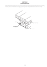
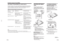
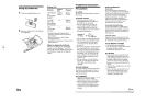
This MiniDisc Recorder is classified as a
CLASS 1 LASER product.
The CLASS 1 LASER PRODUCT label is
located on the buttom exterior.
For customers in Europe
Battery operation time
See “Battery life”
Battery life
Batteries Recording Playback
LIP-8 lithium ion Approx. Approx.
Rechargeable battery 4 hours 7 hours
Two LR6 (size AA) Approx.
Sony alkaline dry batteries 12 hours
LIP-8 + Two LR6 (size AA)
Approx.
22 hours
Dimensions
Approx. 109.5 x 19.7 x 77 mm (w/h/d)
(4
3
/8 x
25
/32 x 3
1
/8 in.)
Mass
Approx. 190 g (6.8 oz) the recorder only
Approx. 240 g (8.5 oz) incl, a recordable MD,
and LIP-8 lithium ion rechargeable battery
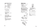
Supplied accessories
AC power adaptor (1)
Headphones with a remote control (1)
LIP-8 lithium ion rechargeable battery (1)
Dry battery case (1)
Ear pads (2)
Carrying case (1)
Design and specifications are subject to change without notice.