


37
MZ-E505
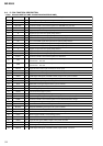
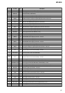
Pin No.
Pin Name
I/O Description
90
SPDW O Spindle motor drive control signal output (W) to the motor driver
91
DSPVDD2
—
Power supply terminal (for DSP block) (+1.5V)
92
DSPVSS1
—
Ground terminal (for DSP block)
93 SPCU I Spindle motor drive comparison signal input (U) from the motor driver
94 SPCV I Spindle motor drive comparison signal input (V) from the motor driver
95 SPCW I Spindle motor drive comparison signal input (W) from the motor driver
96 SDU O Sled motor drive signal output (U) to the motor driver
97 SLVS O Sled servo drive PWM signal output to the motor driver
98 SDV O Sled motor drive signal output (V) to the motor driver
99 SDW O Sled motor drive signal output (W) to the motor driver
100 SLCU I Sled motor drive comparison signal input (U) from the motor driver
101 SLCV I Sled motor drive comparison signal input (V) from the motor driver
102 SLCW I Sled motor drive comparison signal input (W) from the motor driver
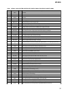
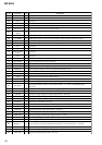
103 DIFVDD1
—
Power supply terminal (for DSP I/F) (+1.9V)
104 DIFVSS1
—
Ground terminal (for DSP I/F)
105 EFMO O EFM encode data output terminal for the record Not used
106 MNT0 O Internal DSP monitor output (0) terminal Not used
107 MNT1 O Internal DSP monitor output (1) terminal Not used
108 MNT2 O Internal DSP monitor output (2) terminal Not used
109 MNT3 O Internal DSP monitor output (3) terminal Not used
110 SENSE O Internal DSP (SENS) monitor output terminal Not used
111 TX O Record data output enable signal output monitor terminal of the internal DSP Not used
112 RECP O Laser power changeover signal output monitor terminal Not used
113 DSPVDD3
—
Power supply terminal (for DSP block) (+1.5V)
114 to
117
NC O Output terminal for the external D-RAM Not used
118 DRAMVSS0
—
Ground terminal (for the external D-RAM)
119 DRAMVDD0
—
Power supply terminal (for the external D-RAM) (+2.3V)
120 to
138
NC O Output terminal for the external D-RAM Not used
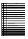
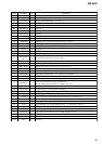
139 DRAMVDD1
—
Power supply terminal (for the external D-RAM) (+2.3V)
140 DRAMVSS1
—
Ground terminal (for the external D-RAM)
141 TSB MST VDD
—
Power supply terminal (for TSB master communication) (+1.9V)
142 RMC DTCK I/O TSB serial data input/output with the remote commander attached headphone
143 TSB SLV VDD
—
Power supply terminal (for I/F to TSB slave communication) (+1.9V)
144 TSB SLVI I TSB slave signal input terminal Not used
145 TSB SLVO O TSB slave signal output terminal Not used
146 TDI I Data input terminal for JTAG Not used
147 TMS I Test mode control input terminal for JTAG Not used
148 TCK I Clock input terminal for JTAG Not used
149 XTRST I Reset input terminal for JTAG Not used
150 TDO O Data output terminal for JTAG Not used
151 JTAGVDD
—
Power supply terminal (for JTAG) (+2.3V)
152 JTAGVSS
—
Ground terminal (for JTAG)
153 MCUVDD2
—
Power supply terminal (for the microcomputer block) (+1.5V)
154 MIFVDD0
—
Power supply terminal (for the microcomputer I/F block) (+1.9V)
155 MIFVSS0
—
Ground terminal (for the microcomputer I/F block)