


36
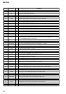
MZ-E505
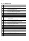
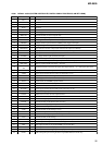
Pin No.
Pin Name
I/O Description
45 BOTM
I
Bottom hold signal input of the light amount signal (RF/ABCD) from RF amp
46 ABCD I Light amount signal (ABCD) input from RF amp
47 FE I Focus error signal input from RF amp
48 AUX1 I Support signal (I
3
signal/temperature signal) input terminal (A/D input) Not used
49 VC I Middle point voltage (+1.2V) input terminal
50 ADIO O Monitor output terminal of A/D converter input signal Not used
51 ADRT I A/D converter the upper limit voltage input terminal (fixed at “H” in this set)
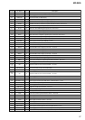
52
AVD2
—
Power supply terminal (for the analog) (+2.3V)
53
AVS2
—
Ground terminal (for the analog)
54
ADRB
I
A/D converter the lower limit voltage input (fixed at “L” in this set)
55
SE
I
Sled error signal input terminal Not used
56
TE
I
Tracking error signal input from RF amp
57
DCHG
—
Connecting analog power supply of the low impedance (fixed at “H” in this set)
58
APC
I
Error signal input for the laser automatic power control Not used
59
DSPVDD0
—
Power supply terminal (for DSP block) (+1.5V)
60
DSPVSS0
—
Ground terminal (for DSP block)
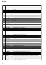
61
XTSL
I
Input terminal for the frequency set up of the system clock “L”: 45.1584MHz,
“H”: 22.5792MHz (fixed at “L” in this set)
62
DIN1
I
Input terminal of the record system digital audio signal Not used
63
DOUT
O
Output terminal of the playback system digital audio signal Not used
64
DAPWMLP O D/A converter PWM output terminal (L-CH right phase) Not used
65
DAPWMLN
O
D/A converter PWM output terminal (L-CH reverse phase) Not used
66
DAPWMRP O D/A converter PWM output terminal (R-CH right phase) Not used
67
DADT O Audio data output terminal Not used
68
ADDT
I
Data input terminal Not used
69
LRCK O L/R sampling clock signal (44.1KHz) output terminal Not used
70
XBCK O Bit clock signal (2.8224MHz) output terminal Not used
71
FS256
O
11.2896MHz clock signal output terminal Not used
72
MVCI
I
Clock signal input terminal Not used
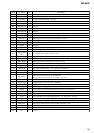
73
DSPVDD1
—
Power supply terminal (for DSP block) (+1.5V)
74
ADFG
I
ADIP duplex FM signal (20.05±1kHz) input from RF amp
75
F0CNT
O
Filter cut off control signal output terminal Not used
76
DIFVDD0
—
Power supply terminal (for DSP I/F) (+1.9V)
77
DIFVSS0
—
Ground terminal (for DSP I/F)
78
APCREF O Reference PWM signal output for the laser automatic power control to RF amp
79
LDDR O PWM signal output for the laser automatic power control Not used
80
TRDR O Tracking servo drive PWM signal output (–) to the motor driver
81
TFDR O Tracking servo drive PWM signal output (+) to the motor driver
82
FFDR O Focus servo drive PWM signal output (+) to the motor driver
83
FRDR O Focus servo drive PWM signal output (–) to the motor driver
84
MCUVDD1
—
Power supply terminal (for the microcomputer block) (+1.5V)
85
FGIN I FG signal input terminal for the spindle CAV servo Not used
86
FS4 O 176.4kHz clock signal output to the power control
87
SPDU O Spindle motor drive control signal output (U) to the motor driver
88
SPVS O Spindle servo drive PWM signal output to the motor driver
89
SPDV O Spindle motor drive control signal output (V) to the motor driver