– 21 –
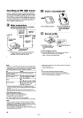
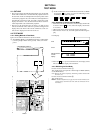
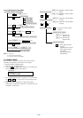
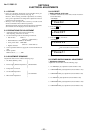
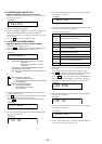
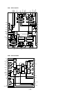
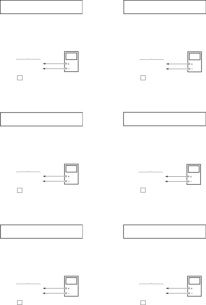
• Adjustment method of VC PWM Duty (L)
(mode number: 762)
1. Select the manual mode of the test mode, and set the mode
number 762. (See page 14)
2. Connect a digital voltmeter to the TP915 (VC) on the MAIN
board, and adjust [VOL +] key (voltage up) or [VOL --] key
(voltage down) so that the voltage becomes 2.5 ± 0.02 V.
Proceed to the next step, if voltage is already adjusted.
3. Press the X key to write the adjusted value.
• Adjustment method of VREM PWM Duty (H)
(mode number: 763)
1. Select the manual mode of the test mode, and set the mode
number 763. (See page 14)
2. Connect a digital voltmeter to the TP914 (VR) on the MAIN
board, and adjust
[VOL +] key (voltage up) or [VOL --] key
(voltage down) so that the voltage becomes 2.75 ± 0.02 V.
Proceed to the next step, if voltage is already adjusted.
3. Press the X key to write the adjusted value.
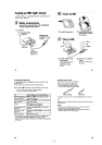
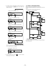
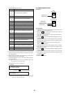
• Adjustment method of VREM PWM Duty (L)
(mode number: 764)
1. Select the manual mode of the test mode, and set the mode
number 764. (See page 14)
2. Connect a digital voltmeter to the TP914 (VR) on the MAIN
board, and adjust
[VOL +] key (voltage up) or [VOL --] key
(voltage down) so that the voltage becomes 2.5 ± 0.02 V.
Proceed to the next step, if voltage is already adjusted.
3. Press the X key to write the adjusted value.
VclPWM
762
LCD display
digital
voltmeter
MAIN board
TP915 (VC)
TP5105 (GND)
VrhVcl
763
LCD display
digital
voltmeter
MAIN board
TP914 (VC)
TP5105 (GND)
VrlVcl
764
LCD display
digital
voltmeter
MAIN board
TP914 (VC)
TP5105 (GND)
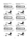
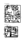
• Adjustment method of VC PWM Duty (H)
(mode number: 765)
1. Select the manual mode of the test mode, and set the mode
number 765. (See page 14)
2. Connect a digital voltmeter to the TP915 (VC) on the MAIN
board, and adjust [VOL +] key (voltage up) or [VOL --] key
(voltage down) so that the voltage becomes 2.5 ± 0.02 V.
Proceed to the next step, if voltage is already adjusted.
3. Press the X key to write the adjusted value.
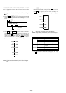
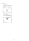
• Adjustment method of VREM PWM Duty (H)
(mode number: 766)
1. Select the manual mode of the test mode, and set the mode
number 766. (See page 14)
2. Connect a digital voltmeter to the TP914 (VR) on the MAIN
board, and adjust
[VOL +] key (voltage up) or [VOL --] key
(voltage down) so that the voltage becomes 2.75 ± 0.02 V.
Proceed to the next step, if voltage is already adjusted.
3. Press the X key to write the adjusted value.
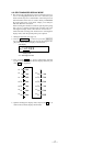
• Adjustment method of VREM PWM Duty (L)
(mode number: 767)
1. Select the manual mode of the test mode, and set the mode
number 767. (See page 14)
2. Connect a digital voltmeter to the TP914 (VR) on the MAIN
board, and adjust
[VOL +] key (voltage up) or [VOL --] key
(voltage down) so that the voltage becomes 2.5 ± 0.02 V.
Proceed to the next step, if voltage is already adjusted.
3. Press the X key to write the adjusted value.
VchPWM
765
LCD display
digital
voltmeter
MAIN board
TP915 (VC)
TP5105 (GND)
VrhVch
766
LCD display
digital
voltmeter
MAIN board
TP914 (VC)
TP5105 (GND)
VrlVch
767
LCD display
digital
voltmeter
MAIN board
TP914 (VC)
TP5105 (GND)