


16
CDX-MP40
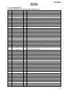
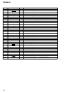
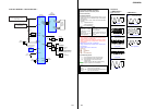
Pin No. Pin Name I/O Pin Description
67 MD2 — CPU operation mode setting pin
68 FL_BOOT I Flash write selection signal input (“L”: flash write mode)
69 FL_W O Flash write control signal output connected to pin 66 (FWE)
70 NC O Not used. (Open)
71 CDMON O CD mechanism power supply control signal output
72 DECINT I Interrupt signal input from the DSP IC
73 CLOSE O Front panel operation request output (Close)
74 OPEN O Front panel oparation request output (Open)
75 LINKOFF O LINK OFF signal output for UNI_LINK “H”: link off, “L”: link on
76 UNI_SO O Sony-Bus serial data output to the bus interface
77 UNI_SI I Sony-Bus serial data input from the bus interface
78 UNI_CK I Sony-Bus serial clock input from the bus interface
79 NC O Not used. (Open)
80 SDA I/O I2C interface data input/output
81 SCL O I2C interface clock output
82 NC O Not used. (Open)
83 TSO O Serial data output to the servo IC
84 TSI I Serial data input from the servo IC
85 TSCK O Serial clock output to the servo IC
86 LEDDAT O LED data output for the jig
87 LEDCLK O LED clock output for the jig
88 LEDLAT O LED latch signal output for the jig
89, 90 NC O Not used. (Open)
91 BUSON I Sony-Bus BUS ON signal input from the bus interface
92 BUCHK I Back up power supply detection signal input
93 A-ATT O Audio muting control signal output
94 CDON O Power control signal output for the CD servo “H”: servo on, “L”: during loading
95 NC O Not used. (Open)
96 U/J_SEL I Destination setting pin
97 TEXTSEL I CD text function setting pin
98 NC O Not used. (Open)
99 CFSEL I Custom file function setting pin
100 DOUT SEL I Digital output selection setting pin “H”: digital output available