


2
CDP-CE575
SAFETY CHECK-OUT
After correcting the original service problem, perform the follow-
ing safety check before releasing the set to the customer:
Check the antenna terminals, metal trim, “metallized” knobs,
screws, and all other exposed metal parts for AC leakage.
Check leakage as described below.
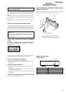
LEAKAGE TEST
The AC leakage from any exposed metal part to earth ground and
from all exposed metal parts to any exposed metal part having a
return to chassis, must not exceed 0.5 mA (500 microamperes.).
Leakage current can be measured by any one of three methods.
1. A commercial leakage tester, such as the Simpson 229 or RCA
WT-540A. Follow the manufacturers’ instructions to use these
instruments.
2. A battery-operated AC milliammeter. The Data Precision 245
digital multimeter is suitable for this job.
3. Measuring the voltage drop across a resistor by means of a
VOM or battery-operated AC voltmeter. The “limit” indica-
tion is 0.75 V, so analog meters must have an accurate low-
voltage scale. The Simpson 250 and Sanwa SH-63Trd are ex-
amples of a passive VOM that is suitable. Nearly all battery
operated digital multimeters that have a 2 V AC range are suit-
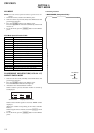
able. (See Fig. A)
Fig. A. Using an AC voltmeter to check AC leakage.
1.5 k
Ω
0.15 µF
AC
voltmeter
(0.75 V)
To Exposed Metal
Parts on Set
Earth Ground
TABLE OF CONTENTS
1. SERVICEING NOTES ............................................ 3
2. GENERAL ................................................................... 6
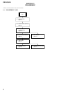
3. DISASSEMBLY
3-1. Disassembly Flow ........................................................... 8
3-2. Case (409538) ................................................................. 9
3-3. Front Panel Section ......................................................... 9
3-4. CD Mechanism Deck (CDM59-5BD27) ........................ 10
3-5. MAIN Board ................................................................... 10
3-6. Base Unit (BU-5BD27)................................................... 11
3-7. Table Assy ....................................................................... 11
3-8. Sensor Board ................................................................... 12
3-9. Loading Motor Board ..................................................... 12
4. ASSEMBLY ................................................................. 13
5. TEST MODE .............................................................. 14
6. ELECTRICAL ADJUSTMENTS ......................... 18
7. DIAGRAMS
7-1. Note for Printed Wiring Boards and
Schematic Diagrams ....................................................... 21
7-2. Printed Wiring Board – BD Section – ........................... 22
7-3. Schematic Diagram – BD Section – .............................. 23
7-4. Printed Wiring Boards
– MOTOR/SENSOR Section – ....................................... 24
7-5. Schematic Diagram – MOTOR/SENSOR Section – .... 25
7-6. Schematic Diagram – MAIN Section (1/2) – ................ 26
7-7. Schematic Diagram – MAIN Section (2/2) – ................ 27
7-8. Printed Wiring Boards – MAIN Section – .................... 28
7-9. Printed Wiring Boards – DISPLAY Section – .............. 30
7-10. Schematic Diagram – DISPLAY Section – ................... 31
7-11. IC Pin Function Description ........................................... 32
8. EXPLODED VIEWS
8-1. Case Section .................................................................... 36
8-2. Front Panel Section ......................................................... 37
8-3. Chassis Section ............................................................... 38
8-4. CD Mechanism Deck Section-1
(CDM59-5BD27) ............................................................ 39
8-5. CD Mechanism Deck Section-2
(CDM59-5BD27) ............................................................ 40
8-6. Base Unit Section (BU-5BD27) ..................................... 41
9. ELECTRICAL PARTS LIST ............................... 42
ATTENTION AU COMPOSANT AYANT RAPPORT
À LA SÉCURITÉ!
LES COMPOSANTS IDENTIFIÉS PAR UNE MARQUE 0
SUR LES DIAGRAMMES SCHÉMATIQUES ET LA LISTE
DES PIÈCES SONT CRITIQUES POUR LA SÉCURITÉ
DE FONCTIONNEMENT. NE REMPLACER CES COM-
POSANTS QUE PAR DES PIÈCES SONY DONT LES
NUMÉROS SONT DONNÉS DANS CE MANUEL OU
DANS LES SUPPLÉMENTS PUBLIÉS PAR SONY.
SAFETY-RELATED COMPONENT WARNING!!
COMPONENTS IDENTIFIED BY MARK 0 OR DOTTED
LINE WITH MARK 0 ON THE SCHEMATIC DIAGRAMS
AND IN THE PARTS LIST ARE CRITICAL TO SAFE
OPERATION. REPLACE THESE COMPONENTS WITH
SONY PARTS WHOSE PART NUMBERS APPEAR AS
SHOWN IN THIS MANUAL OR IN SUPPLEMENTS PUB-
LISHED BY SONY.
Ver 1.1 2001.07