


iPort ver. IW
Instruction Manual
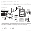
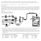
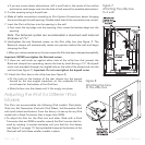
11. For IW-5 Systems:
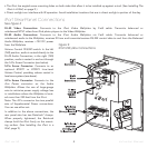
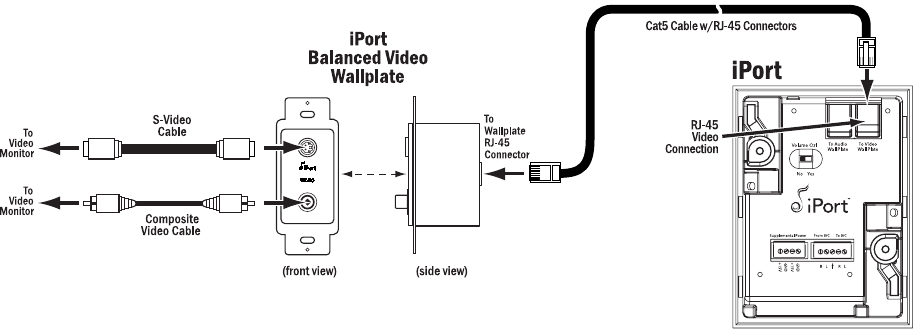
11a. Plug the video Cat5 cable’s RJ-45 connectors into the
Video
jacks on the iPort and the RJ-45 connector on the Video
Wallplate, as shown above in
Figure 6
.
11b. Install the iPort Video Wallplate in an electrical box in the room where the audio equipment is located.
Important: Do
not
install an iPort Wallplate in the same electrical box as AC house wiring, a light switch or any
other high-voltage device or control. The Wallplates can share gang boxes with each other, or with other controls
such as A/B speaker switches, infrared receivers and volume controls, if these other devices are rated as Class 2
devices according to the National Electrical Code.
11c. Connect the Video Wallplate to the video monitor or video distribution system as shown above in
Figure 6
.
Note: You can use both the S-Video and composite video connections simultaneously, if required.
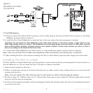
12. After installing the iPort in the wall (see
Installing the iPort in a Wall,
below), plug the power supply into a wall outlet.
Installing the iPort in a Wall
The iPort features an integral RotoLock
®
mounting system for quick mounting directly into existing walls. Once the hole is cut
and the cables are run, you can install the iPort in the wall in a matter of seconds.
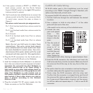
1. Determine the location for the iPort.
2. Perform an obstruction survey to be certain that there are no studs, conduit, pipes, heating ducts or air returns that will
interfere with the iPort.
Note: You can mount the iPort directly next to wall studs on either side (see Step 9, below).
3. The iPort cutout is 4” (102mm) wide x 5
9
/16” (141mm) high. There also must be at least 3½” (89mm) depth within the wall
cavity for the iPort and its connections.
4. Find the cutout template provided in the iPort packaging. Position the template where the iPort is to be located and pencil
an outline on the wall.
Figure 6:
IW-5 Balanced Video
Connections
9