


8
iPort ver. IW
Instruction Manual
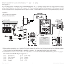
3. Set the iPort’s Volume Control YES/NO switch to the left (NO) position (no volume control in system).
• The iPort’s volume control circuit will affect all zones in a multi-zone system. It is designed for use only in a local-zone system.
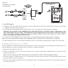
4. Plug the audio Cat5 cable’s RJ-45 connectors into the
Audio
jack on the iPort and the RJ-45 connector on the Audio Wallplate.
5. Install the iPort Audio Wallplate in an electrical box in the room where the audio equipment is located.
Important: Do
not
install an iPort Wallplate in the same electrical box as AC house wiring, a light switch or any
other high-voltage device or control. The Wallplates can share gang boxes with each other, or with other controls
such as A/B speaker switches, infrared receivers and volume controls, if these other devices are rated as Class 2
devices according to the National Electrical Code.
6. Plug the included 15V DC power supply into the
Power
connector on the Wallplate.
7. Use a stereo RCA audio cable to connect the Wallplate to a source input on the audio system.
8. If the audio system has a compatible IR control output, use a mono 3.5mm mini cable to connect it to the Wallplate’s
IR
connector.
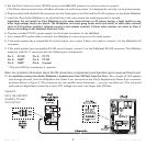
9. If the audio system has a compatible RS-232 control output, connect it to the Wallplate’s RS-232 connector. The Wallplate
accepts a male RJ-11 connector with the following pin configuration:
* Only one GND pin connection is required.
Note: For complete information about RS-232 connections, programming and operation go to www.iportmusic.com.
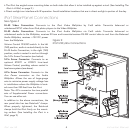
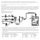
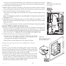
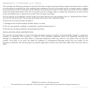
10. In installations where the Audio Wallplate is located more than 250 feet from the iPort: Run a length of 16/2 speaker
wire through the wall, from the Wallplate’s
Aux Power
2-pin connector to the iPort’s
Supplemental Power
4-pin connector
as shown below in
Figure 5
. (The connector has two parallel sets of terminals — you can use either set.) This will avoid
performance degradation caused by a loss of DC voltage over wire runs longer than 250 feet.
Figure 5:
IW-3, IW-4 & IW-5
Auxiliary Power
Connection
Pin 1: PC RX
Pin 2: GND*
Pin 3: GND*
Pin 4: PC TX
Pin 5: PC RX
Pin 6: Unused