


7
iPort ver. IW
Instruction Manual
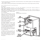
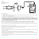
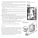
7. Use a stereo RCA audio cable to connect the iPort Wallplate to a source input on the local-zone audio system.
8. After installing the iPort in the wall (see
Installing the iPort in a Wall,
page 9), plug the power supply into a wall outlet.
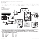
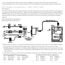
iPort System Connections — IW-3 / IW-4 / IW-5
See
Figure 4
IW-3, IW-4 and IW-5 systems have balanced audio output that is designed for use in audio systems where the audio equipment
is located up to 500 feet from the iPort. In addition to being controlled from its front panel and by an optional #70031 or
#70032 IR remote control, the iPod in IW-3 systems can be controlled by non line-of-sight IR control devices. In IW-4 and IW-5
systems the iPod can also be controlled by RS-232 control devices, with 2-way communication (including iPod metadata).
1. Before making connections, run a length of Cat5 cable through the wall from the iPort location to the iPort Wallplate location.
• Find a location for the Balanced Audio Wallplate that is near both the audio system and a source of AC power.
• For IW-5 systems: Find a location for the Balanced Video Wallplate that is near the video monitor. Run a second Cat5 cable
through the wall from the iPort location to the Balanced Video Wallplate location. Maximum length for the video Cat5
cable is 250 feet.
2. Install RJ-45 connectors on both ends of the Cat5 cables as explained in the
Cat5/RJ-45 Cable Wiring
sidebar on page 6.
The Balanced Audio RJ-45 pin assignment is: The Balanced Video RJ-45 pin assignment is:
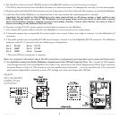
Figure 4:
IW-3, IW-4 & IW-5 Long-Distance
Balanced Audio Connections
Pin 1: Data Receive
Pin 2: Data Transmit
Pin 3: Audio Left +
Pin 4: Audio Left –
Pin 5: Audio Right +
Pin 6: Audio Right –
Pin 7: Ground
Pin 8: +15V
Pin 1: B Video +
Pin 2: B Video –
Pin 3: S-Video C +
Pin 4: S-Video C –
Pin 5: S-Video Y +
Pin 6: S-Video Y –
Pin 7: Ground
Pin 8: +15V