


4
iPort ver. IW
Instruction Manual
• The iPort has angled screw mounting holes on both sides that allow it to be installed up against a stud. (See
Installing The
iPort In A Wall
, on page 9.)
• Direct sunlight can interfere with IR operation. Avoid installation locations that are in direct sunlight a portion of the day.
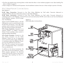
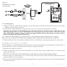
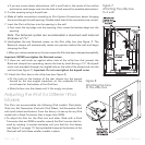
iPort Rear-Panel Connections
See
Figure 2
RJ-45 Video Connection: Connects to the iPort Video Wallplate by Cat5 cable. Transmits balanced or
unbalanced NTSC video from iPod photo players to the Video Wallplate.
RJ-45 Audio Connection: Connects to the iPort Audio Wallplate via Cat5 cable. Transmits balanced or
unbalanced audio to the Wallplate; receives IR from and transmits/receives RS-232 control data to and from the Balanced
Audio Wallplate; receives +15V DC power
from the Wallplate.
Volume Control YES/NO switch: In the left
(
NO
) position, audio is routed directly to the
RJ-45 Audio Connection; in the right (
YES
)
position, audio is routed in and out through
the 5-Pin Screw Connector (see below).
5-Pin Screw Connector: Connects to an
optional #70071 or #70072 Line-Level
Volume Control, providing volume control in
local-zone systems (see above).
4-Pin Screw Connector: Connects to the
Aux Power
connector on the Audio
Wallplate. Allows the use of large-gauge
wire to minimize power supply voltage loss
in installations where the Wallplate is locat-
ed more than 250 feet from the iPort.
Note: The 4-Pin connector has two parallel
sets of Supplemental Power connections.
You can use either set.
In addition to the above connections, the
rear panel also has two RotoLock
®
clamps.
When properly tightened, the RotoLock
clamps hold the iPort firmly on the mount-
ing surface. (See
Installing the iPort in a
Wall
, page 9.)
Figure 2:
iPort Utility Box Connections