


5
iPort ver. IW
Instruction Manual
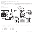
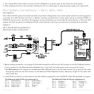
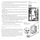
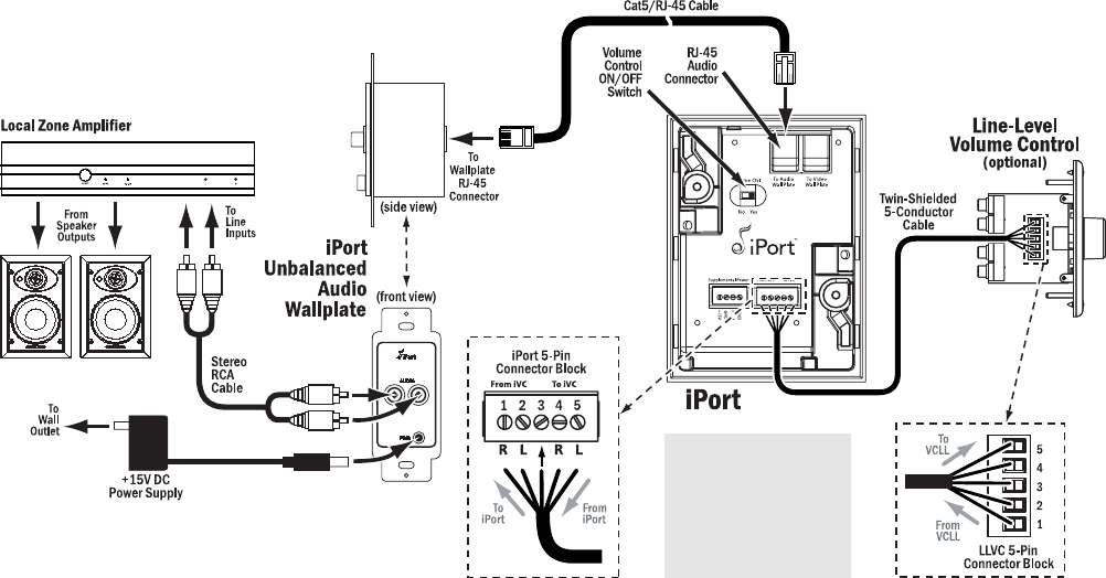
iPort System Connections — IW-1 / IW-2
See
Figure 3
IW-1 and IW-2 systems’ unbalanced audio output is designed for use in a local-zone system where the audio equipment is locat-
ed less than 20 feet from the iPort. In IW-1 systems the iPod is controlled only from its front panel; in IW-2 systems the iPod
can be controlled from its front panel or from an optional #70031 or #70032 IR remote control (or compatible 3rd-party remote).
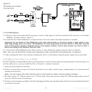
1. Before making connections, run a length of Cat5 cable through the wall from the iPort location to the iPort Wallplate location.
• Find a location for the Wallplate that is near both a source of AC power and the local-zone audio system.
2. Install RJ-45 connectors on both ends of the Cat5 cable as explained in the
Cat5/RJ-45 Cable Wiring
sidebar on page 6.
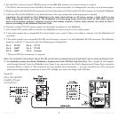
The unbalanced audio RJ-45 pin assignment is:
Pin 1: R ch from VCLL to iPort
Pin 2: L ch from VCLL to iPort
Pin 3: Ground
Pin 4: R ch from iPort to VCLL
Pin 5: L ch from iPort to VCLL
VOLUME CONTROL
WIRING
Figure 3:
IW-1 & IW-2 Local-Zone
System Connections
Pin 1: Data Receive
Pin 2: Data Transmit
Pin 3: Audio Left
Pin 4: Unused
Pin 5: Audio Right
Pin 6: Unused
Pin 7: Ground
Pin 8: +15V