


iPort ver. IW
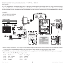
3a. If the system includes a #70071 or #70072 line-
level volume control, set the iPort’s Volume
Control YES/NO switch to the right (
YES
) position
(volume control in system).
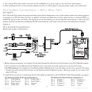
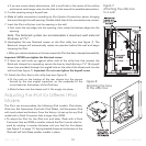
3b. Use 5-conductor twin-shielded wire to connect the
volume control to the iPort 5-pin connector block.
To avoid noise, connect the wires as shown in
Figure 3
.
The volume control connector pin assignments are:
Pin 1: R ch line-level audio from volume control to
iPort
Pin 2: L ch line-level audio from volume control to
iPort
Pin 3: Ground
Pin 4: R ch line-level audio from iPort to volume
control
Pin 5: L ch line-level audio from iPort to volume
control
Note: Do not use Cat5 wire to make these
connections. This wire carries high-imped-
ance unbalanced line-level audio and must
be twin-shielded to avoid noise. Two stan-
dard stereo RCA audio cables with the ends
removed will also work for this application.
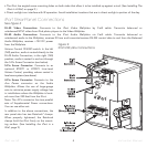
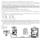
4. Plug the RJ-45 connectors into the
Audio
jack on
the iPort and the RJ-45 jack on the Wallplate.
5. Install the Unbalanced Audio Wallplate in an electrical
box in the room where the audio equipment is located.
Important: Do
not
install the iPort Wallplate in
the same electrical box as AC house wiring, a
light switch or any other high-voltage device or
control. The Wallplate can share gang boxes with
other iPort Wallplates or with controls such as
A/B speaker switches, infrared receivers and vol-
ume controls, if these other devices are rated as
Class 2 devices according to the National
Electrical Code.
6. Plug the included 15V DC power supply into the
Power
connector on the iPort Wallplate.
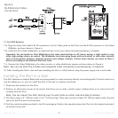
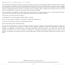
Cat5/RJ-45 Cable Wiring
All RJ-45 cables used in iPort installations must be wired
according to the T568A (“Straight-Through”) Standard, with
cables wired identically at both ends.
To prepare Cat5/RJ-45 cables for iPort installations:
1. Pull the Cat5 wire through the wall between the desired
locations.
2. Use a stripper or knife to strip about 1” of the cable
jacket off each end of the wire.
• Be careful not to nick any of the individual wires.
3. Untwist the wire
pairs and spread
them flat.
Arrange them as
shown in the dia-
gram.
4. Trim the ends of
the individual
wires to ½” in
length, making
sure that they are
even with each
other. Flatten the
wires against each other, leaving no space between them.
5. Hold the RJ-45 connector clip side-down and insert the
Cat5 wire ends firmly into the connector. Make sure that all
the wires are flat all the way to the very front of the con-
nector.
6. Re-confirm that the color orientation matches the diagram
and that cable jacket fits against the connector stop.
7. Firmly crimp the RJ-45 connector with the crimp tool.
Confirm that the connector is crimped firmly and that all
the wires are flat right up against the front of the connec-
tor. If even one of these wires is incorrect, cut the connec-
tor off the cable and repeat steps 2 – 7 with a new RJ-45
connector.
6
Instruction Manual