


14 Russound CA4 System Installation Manual
INSTALLATION
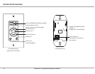
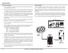
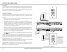
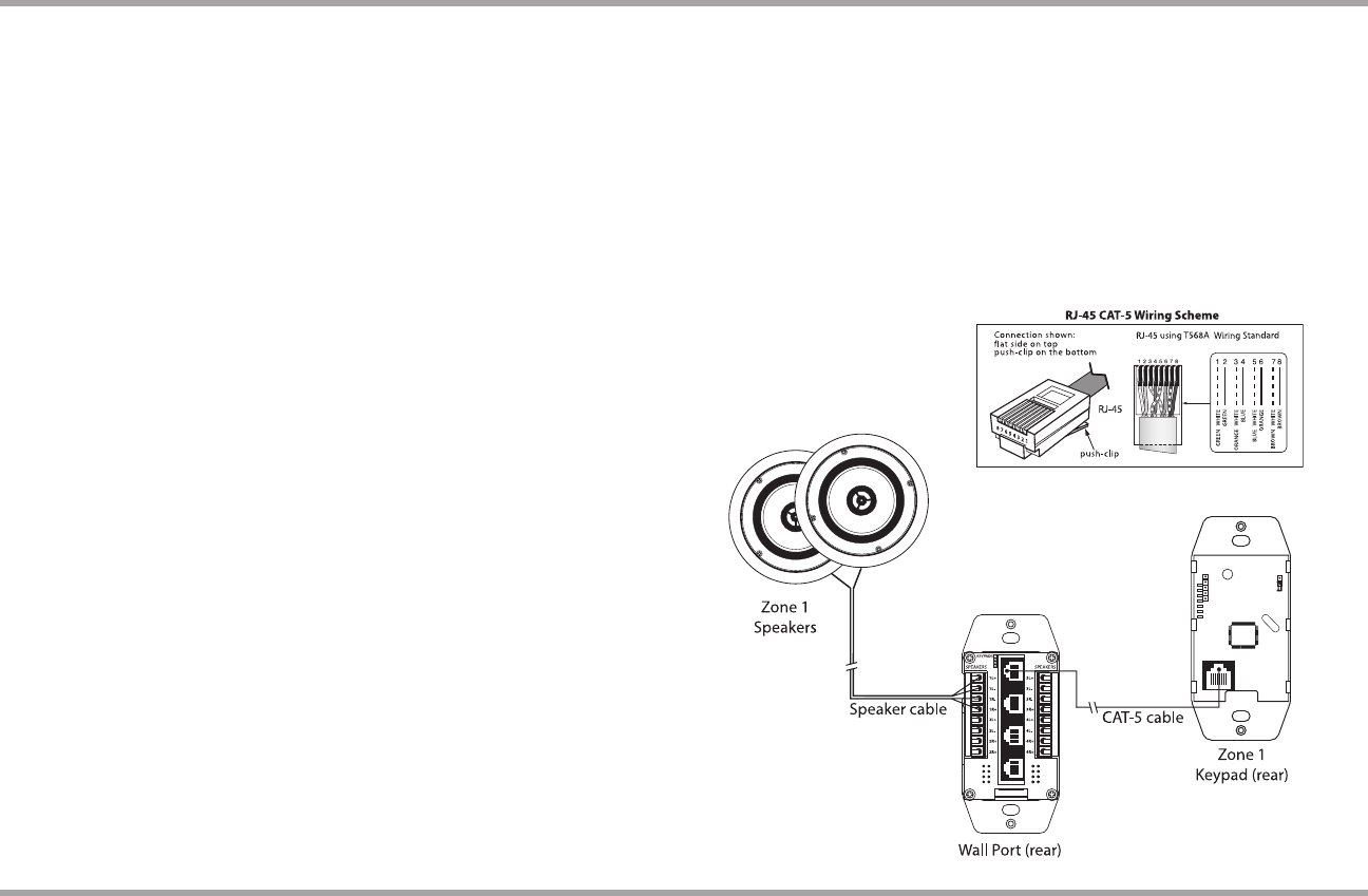
Wall Port Installation
Pick an unobtrusive location close to the controller that all cables (speaker 1.
and keypad) can be routed to.
Install an electrical box, using a UL/CSA approved plastic single-gang (18 2.
ci or deeper) electrical box. If there will be two controllers you should use
two single-gang boxes separated slightly to allow space for the cables.
Route CAT-5 wire from the electrical box to the four keypad locations. Route 3.
the speaker cable from the electrical box to the corresponding speaker
locations. Label each set of cables with the zone and location.
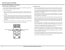
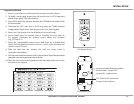
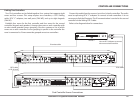
Terminate each CAT-5 wire with a RJ-45 plug using the T568A standard 4.
conguration.
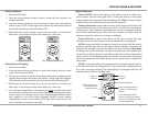
Strip 1 to 2 inches (2.5 to 5 cm) o the end of each speaker cable jacket. 5.
Then strip 1/4 inch (0.7 cm) of insulation o each wire.
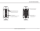
Twist the speaker wire strands together so there are no strands separated 6.
from the bundle.
Insert the proper speaker wire, matching channel and polarity for all four 7.
wires. Tighten the screws until the wires are secured in the terminal.
Cable as follows (standard 4-conductor):
White -- L+ (left channel positive)
Green -- L- (left channel negative)
Black -- R- (right channel negative)
Red -- R+ (right channel positive)
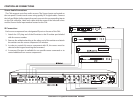
Check to make sure there are no stray strands of wire outside the terminals. 8.
If there are, remove the wire, twist the strands together, and reconnect
the wire to the terminal.
Complete the same steps for the remaining zones. Plug each of the RJ-45 9.
plugs into the corresponding keypad zone jack on the rear of the wall
port. Note: All four connections from the controller to the wall port must
be made, even if there are less than 4 keypads connected to the system.
Cables between the wall port and the controller must match numerically
(#1 on the wall port to #1 on the controller).
Mount the wall port in the electrical box. Push any extra cable back into 10.
the wall. Screw the wall port plate to the electrical box. Attach the trim
plate to the wall port.
/
/
/
/
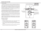
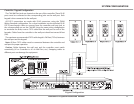
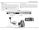
Speaker Outputs
The CA4 supports speaker outputs for zones 1 through 4 for each controller
with a maximum of eight zones. Each speaker connection requires a 8-ohm
load and will provide 15 watts per channel. Standard 16-gauge 4-conductor
stranded speaker wire can be run up to 125 feet; 14-gauge wire can be run up
to 250 feet.
The speakers are connected to the CA4 Wall Port using xed screw terminals.
Each of these terminals is designated for the speaker set of a particular amplied
zone. To avoid confusion, connect one zone speaker set at a time starting with
Zone 1, taking care to keep zone and speaker wire identities straight.