


A 4 ohm speaker may experience a drop in impedance 4-
6 times lower than its nominal (printed) impedance. A
speaker will also create phase shifts in the signal that is
passed through it. These phase shifts happen because
a speaker is an inductor (voice coil) and a capacitor
(compliance of the surround/spider), as well as a resistor
(voice coil wire).
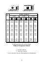
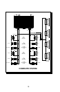
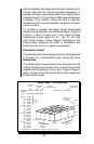
To simulate a speaker the Audio Graph PowerCube
measures output power into 20 different loads. It tests at
8 ohms, 4 ohms, 2 ohms and 1 ohm. Each of these
impedances is also tested at –60°, –30°, 0°, +30° and
+60° phase angles. These different impedances and
phase angles represent the shifts in impedance and
phase that can occur in a typical loudspeaker.
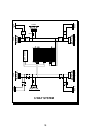
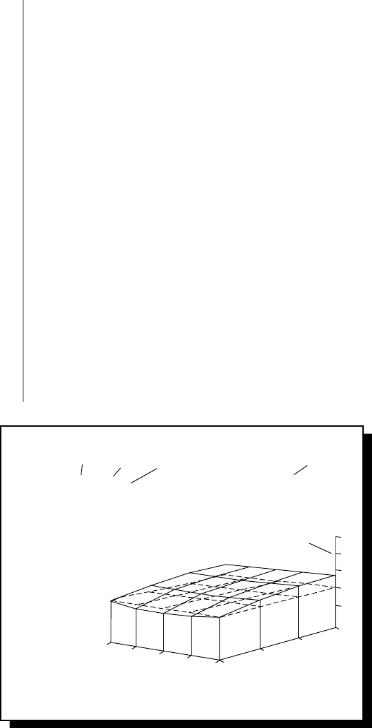
Information Cubed
The data acquired in the testing procedure is then graphed
in the form of a 3-dimensional cube. Hence the name
PowerCube.
The
Phase Angle
is expressed on the horizontal axis, the
Output Voltage
is presented on the vertical axis and the
Impedance
is displayed on the Z axis.
Output Power,
in
watts, is listed on the left hand side for each impedance
at each phase angle.
25
–60° (Cap)
0°
(Ind) +60°
1Ω
2Ω
4Ω
Impedance
8Ω
10V
30V
50V
8Ω –60°
–30°
0°
30°
60°
4Ω –60°
–30°
0°
30°
60°
2Ω –60°
–30°
0°
30°
60°
1Ω –60°
–30°
0°
30°
60°
84 W
84 W
83 W
84 W
85 W
159 W
154 W
153 W
154 W
158 W
266 W
251 W
245 W
248 W
261 W
378 W
343 W
333 W
339 W
373 W
*If a Bridged/Mono, test amplifier sees 1/2 impedance (2Ω test amp sees 1Ω)
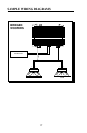
Audio Graph – The PowerCube
Amplifier:
Serial No:
Owner :
PUNCH 200 14.4V x 2
ROCKFORD CORPORATION
Rated Power : 75W at 4 Ohms
IMPEDANCE
MANUFACTURERS
RATED OUTPUT
MODEL BEING
TESTED
x2 = STEREO
MONO = BRIDGED MONO*
VOLTAGE FROM
BATTERY
OUTPUT VOLTAGE
AT THE RAILS
(MOSFETS)
*
*
*
*
PHASE ANGLES
"MOTION OF
SPEAKER"
{
POWER
IN
WATTS
{
{