


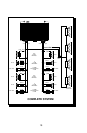

The GND terminal grounds the amplifier and is connected
to the chassis of the vehicle with 12 gauge, or heavier,
stranded wire. To prevent ground loops, we recommend
you refrain from extending the ground wire beyond 18"
(45.72cm) in any installation. The ends of the Power and
Ground wires that are connected to the amplifier should
be stripped back 5/8” (1.59cm).
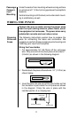
The Punch amplifiers are turned on by supplying positive
(+) 12 volts to the REM terminal. Usually the terminal is
connected to the source unit’s “Accessory” or “Auto
Antenna” lead, either of which will go to +12 Volts when
the source unit is turned on.
Although the majority of high-quality automotive source
units have an Accessory or Antenna output, there are
many which require different turn-on methods. If the
source unit has no Auto Antenna lead (or if the Auto
Antenna goes down during tape operation):
a. Find the internal switched power voltage inside
the source unit and solder a lead to it. Run the
lead out through the back of the unit (being sure
to use a grommet for insulation from the case)
and connect the Punch remote turn-on wire; or:
b. Install a switch in the car with one terminal
connected to +12 volts and the other to the Punch
lead.
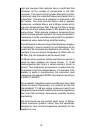
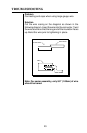
The amplifier’s signal input RCA jacks should be con-
nected to the source unit’s signal outputs with high-quality
braided or double-shielded interconnecting RCA cables.
Note: Be sure to route the Punch signal input cable
away from the main power wire and the car’s wiring
harnesses to avoid noise coupling.
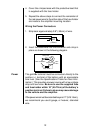
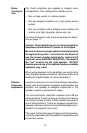
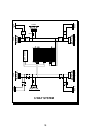
Punch amplifiers are rated for safe operation into loads of
2Ω or greater in stereo mode or 4Ω in bridged mono
configurations. The primary loads on any amplifier come
from directly connected speakers without using capaci-
tors. The measured resistance for each side should not
be less than 2Ω.
13
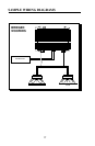
Ground
Remote
Turn-on
Input
Speakers