


Appendix A - Test and Operating Data
Cassette Data Test
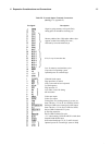
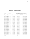
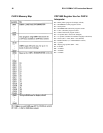
Load the following machine language program into memory:
0000 90 B6 B3 F8 33 A6 F8 OA
0008 A3 D3 F8 6F AC F8 40 B9
0010 93 F6 DC 29 99 3A 10 F8
0018 10 A7 F8 08 A9 06 B7 F8
0020 80 FE DC 97 F6 B7 DC 29
0028 89 3A 23 17 87 F6 DC 30
0030 17 30 31 35 00 00 00 00
Rewind a blank cassette and put recorder into record
mode. Wait 10 seconds and flip RUN up to initiate the
program. The byte at location 0033 will be continuously
recorded on tape. Flip RUN down to stop recording after
a minute or so. You can play this tape to check the
signals shown below. You can also load the tape into
memory for testing purposes. Load 7 pages starting at
0100. You can use this tape to determine the proper
volume control setting for your recorder. You can change
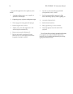
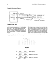
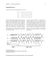
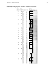
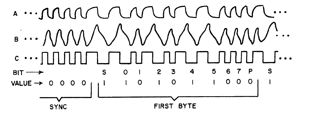
the recorded byte at 0033 if desired. Bits on tape consist
of one cycle at 2 kHz for
31
"0" or one cycle at 0.8 kHz for "1". Data format is 4
seconds of continuous "0's" for sync followed by the
specified number of data bytes. Bytes always begin with
a "1" start bit (S) followed by 8 data bits (0-7), and end
with a parity bit (P). Odd byte parity is used in this code.
The waveforms below show how a 35 byte would appear
on tape. The operating system translates memory bytes to
bit serial output via the Q output line. Bit serial input
from tape is received via input flag 2 and translated into
parallel form for storage in memory by the operating
system software.
A-OUTPUT OF U14A
B-OUTPUT FROM CASSETTE (TAP IN PAD ON CARD)
C-OUTPUT OF U14B
* WAVEFORMS SHOWN FOR PANASONIC MODEL RO-413S RECORDER.