


24
A single photocell input could be provided via the
buffered EF4 line. You can attach the photocell
directly between the L and Z pads. Experimentally
adjust the pull-up resistor on pad L for best
operation. No photocell amplifier should be required
to drive the COS/MOS input. An, externally supplied
positive pulse- on. Pins 2_and 14 of U25,can be used as
an input,byte- strobe when yow want to latch an input
byte into U25. A 68 can be used to store
this input byte in RAM.
Using the Expansion
Interface
The 44-pin card socket for the expansion interface
pads along the back left edge of the PC board permits
extensive expansion. If you expand beyond the
capabilities of the power converter provided with the
VIP, you will, of course, have to provide your own power
supply. Output signals should only drive COS/MOS
loads, and must be externally buffered with a. CD4050
or CD4049 IC to drive TTL loads. Keep any wires
connected to the expansion pad signals as short as
possible. Excessive stray capacitance on these signal
lines can interfere with proper operation of the computer.
Input signals should also be buffered with COS/MOS
circuits. Refer to the. machine language programming
section (Section IV) and the logic diagrams (Appendix E)
to avoid conflicts with normal COSMAC VIP use of
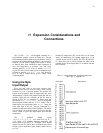
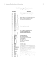
these signals. The external option terminal connections
are given in Table III.
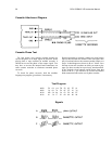
You can latch up the required high order address bits
with the trailing edge of TPA when adding external
memory. You must provide a Positive level on pad 19 to
disable internal RAM when external RAM is addressed.
The operating system will always use the highest page of
internal (on-card) RAM, even when you add external
RAM.
If you wish to substitute an external ROM or
battery-powered COS/MOS RAM for U10, you can use
the signal on pad X to select it. Remove U10 when
substituting an external ROM. If you do use an external
ROM for your own operating system you may no longer
be able to use the CHIP-8 interpreter because it requires
some of the operating system subroutines.
The expansion interface pads provide access to all
CDP1802 signals so that you can add any desired
external circuits.
Only 5 out of the possible 14 CDP1802 input/output
instructions are used internally, so that you can externally
decode the N0, N1, and N2 lines and use them with MRD
to obtain the use of the remaining 9 input/output
instruction codes. You can
I
RCA COSMAC VIP Instruction Manual
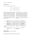
also latch high-order address bits to select external
devices if desired. When using external circuits to
generate DMA requests, interrupt requests, or input flag
signals, isolate these signals with 1N914 diodes as shown
for EF3 and EF4 in the optional parallel input/ output
port logic. Refer to the User Manual for the CDPI802
COSMAC Microprocessor, MPM-201A, for specific
examples of input/output attachment techniques.
Some Expansion Ideas
The August and September 1976 issues of Popular
Electronics contain descriptions of a COSMAC ELF
microcomputer using the CDP1802. These articles
illustrate some input/output attachment techniques.
The following lists some things that with some
exercise of your ingenuity could be added to your system
at relatively low cost:
1. Manually operated photoelectric paper-tape strip
reader. Only requires a tape guide and 8
photocells.
2.
S
cann
i
n
g
c
i
rcu
i
t
f
or mu
l
t
ipl
e
i
n
p
ut
li
nes
f
rom
sens
i
n
g
d
ev
i
ces us
i
n
g
CD4515
IC
.
3. Full alphanumeric keyboard.
4. Low-cost printer.
5. Multi-digit numeric display.
6. Calculator chip.
7. Individual photocells or switches.
8. Output relays to control solenoids, bells,
whistles, sirens, lights, or motors.
9. Sound-generating circuits that can be controlled
by program.
10. Analog-to-digital input circuits.
11.
Read-Only Memory for fixed program.
12. Digital-to-analog output circuits.
13.
Alpha wave monitor input to control pictures on
TV or output devices.
14. Temperature- or pressure-sensing devices.
15.
16.
Computer terminal.
A second hex keyboard for multi-player video
games.