


V1. Expansion Considerations and
Connections
The
COSMAC VIP
was designed primarily as a
self-contained graphic system for home use. Enough
RAM and input/output features are provided for years of
computer fun without adding anything to your system. If,
however, you do want to expand your system, a variety
of features have been included to make expansion as
easy and inexpensive as possible. You can easily
increase RAM to
4096
bytes by adding
U20-U23
to your PC card. Use the same type or a compatible type
of RAM as used for
U16-U19. You
may, however,
have to add a higher-current power supply when
expanding RAM.
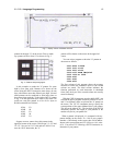
Using the Byte
Input/Output
First, you may wish to add some external com-
puter-controlled devices such as relays, input sensing
switches, or even a low-cost printer. The printer will
require an 8-bit parallel input or output port and some
"hand-shaking" signals. One parallel input port and one
parallel output port are available on the PC card as
shown in Fig. E-5 in Appendix E. These ports are
provided by
U24, U25, U26,
and U27 along with
the associated resistors and two
IN914
diodes. The 22
input/output port connection pads
(A-Z)
along the
back right edge of the PC card are connected to a
standard 44-pin card socket on the COSMAC VIP board.
You can plug your external circuits or devices into this
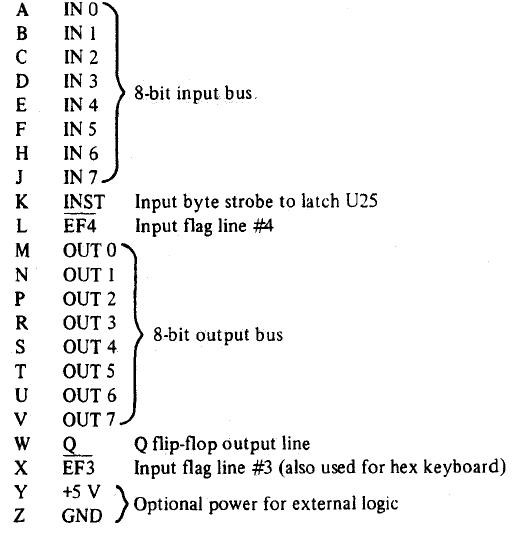
socket. Table II gives the input/output port terminal
connections.
The 8 buffered output signals
(M,N,P,R,S,T,U,V)
will each drive up to
2
TTL
loads. A 63 machine language instruction will
latch a memory byte into
U24
for output. The 8 latched
output lines can be used to drive individual relay driver
circuits, power amplifiers, lights, battery motor drivers,
etc. The
23
buffered Q output line (W) can be used as an output
strobe for transferring the latched output byte to an
external device such as a printer. The EF3 (X) and EF4
(L) input fines can be used to indicate the status of an
external device. Don't forget that EF3 is shared with the
hex keyboard.
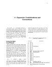
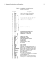
Table 11 - Input/Output Port Terminal Connections
(See Fig. E-5, Appendix E)
Pin Signal Description