


21
V. Logic Description
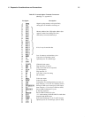
A complete set of logic diagrams is provided in
Appendix E. Power requirements for a system with 2048
bytes of RAM is 5 V DC at 350 mA. If you wish to
expand the system you can use your own higher current
power supply.
This system is designed around the CDP1802
microprocessor Wfl. Refer to the CDP1802 data sheet
and User Manual for the CDPI802 COSMAC
Microprocessor MPM-201A for a complete description
of its operation. The CDP1802 requires a square-wave
clock input at pin 1 for operation. This system uses a
1.7609-MHz clock. One half of U3 is connected as a
free-running crystal-controlled oscillator. A
3.52180-MHz crystal is used in this circuit. The output of
this 3.52180-MHz oscillator is then divided by 2 using
U4 to provide the 1.7609MHz input clock for the
CDP1802. Because each CDP1802 machine cycle equals
8 clock cycles, each machine cycle is about 4.54 us in
duration. TPA and TPB are timing pulses generated once
each machine cycle by the CDP 1802 microprocessor.
How Memory Is Addressed
A debounced RUN level goes high when the RUN
switch is flipped up. This signal causes the CDP1802 to
begin fetching instructions from memory. When the
RUN switch is down, the CDP1802 is held in a reset
state and U6A (in Fig. E-2) is reset. U6B is held set by
U6A. The CDP1802 starts fetching instructions from the
ROM (U10) at location 8000 since UOB is being held
set. The ROM contains the
operating system program which uses a 64 instruction to
generate an N2 pulse. This-N2 pulse sets U6A so it no
longer holds U6B in its set state. From this point on, the
selection,of RAM or ROM locations is controlled by the
most significant address bit latched into U6B each cycle
by TPA.
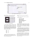
U8 latches an additional 4 address bits to provide the
1-9-bit address required in a 4096-byte RAM system.
U9A decodes 2 of these address bits into 4 lines which
are used to select up to four 1024-byte RAM sections.
Each 1024-byte section of RAM consists of two 4 x
1024-bit RAM IC's (U16-U23 in Fig. E-4). Only the first
two sections of RAM (U16-U19) are used in a 2048-byte
system. U9B in Fig. E-2 is wired as a simple gate that
inhibits selecting any section of RAM when either the
ROM is selected or a positive RAM inhibit signal is
generated on pin 19 of the expansion interface by
external circuits.
Memory read (MRD) and write (MWR) signals are
supplied to the RAM at appropriate times by the
CDP1802. Data is transferred between memory,
CDP1802, input, or output via an 8-bit data bus. Pull-up
resistors are provided on this bus for compatibility with
TTL signal swings provided by some RAMs.
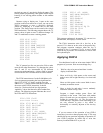
How the Input/Output Works
Ull and U12 in Fig. E-3 are used to decode the
input/output instruction codes used in the system.
U13 provides the hex keyboard interface. This
interface permits a program to determine which key is