


14
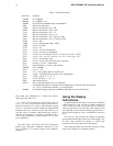
Table I - CHIP-8 Instructions
RCA COSMAC VIP Instruction Manual
Instruction Operation
1MMM Go to 0MMM
BMMM Go to 0MMM + V0
2MMM Do subroutine at 0MMM (must end with 00EE)
00EE Return from subroutine
3XKK Skip next instruction if VX = KK
4XKK Skip next instruction if VX n.e. KK
5XY0 Skip next instruction if VX = VY
9XY0 Skip next instruction if VX n.e. VY
EX9E Skip next instruction if VX = Hex key (LSD)
EXAl Skip next instruction if VX n.e. Hex key (LSD)
6XKK Let VX = KK
CXKK Let VX = Random Byte (KK = Mask)
7XKK Let VX=VX+ KK
8XY0 Let VX = VY
8XY1 Let VX = VX/VY (VF changed)
8XY2 Let VX = VX & VY (VF changed)
8XY4 Let VX=VX +VY(VF=00 if VX+VY l.e. FF,VF=01 if VX +VY>FF)
8XY5 Let VX = VX - VY (VF = 00 if VX < VY, VF = 01 if VX g.e. VY)
FX07 Let VX = current timer value
FX0A Let VX = hex key digit (waits for any key pressed)
FX15 Set timer = VX (01 = 1/60 second)
FX18 Set tone duration = VX (01 = 1/60 second)
AMMM Let I = 0MMM
FX1E Let I = I + VX
FX29 Let I = 5-byte display pattern for LSD of VX
FX33 Let MI = 3-decimal digit equivalent of VX (I unchanged)
FX55 Let MI = V0:VX (I = I + X + 1)
FX65 Let V0: VX MI (I = I + X + 1)
00E0 Erase display (all 0's)
DXYN Show n-byte MI pattern at VX-VY coordinates.
I unchanged. MI pattern is combined with existing display via EXCLUSIVE-OR function.
VF = 01 if a 1 in MI pattern matches 1 in existing display.
0MMM Do machine language subroutine at 0MMM (subroutine must end with D4 byte)
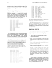
three RAM bytes addressed by I contain the decimal
equivalent of the value of V9.
If 1 =0327, a F355 instruction will cause the values of
VO, V1, V2, and V3 to be stored at memory locations 0327,
0328, 0329, and 032A. If 1=0410, a F265 instruction would
set V0, V1, and V2 to the values of the bytes stored at RAM
locations 0410, 0411, and 0412. FX55 and FX65 let you
store the values of variables in RAM and set the values of
variables to RAM bytes. A sequence of variables (V0 to
VX) is always transferred to or from RAM. If X = 0, only
VO is transferred.
The 8XYI, 8XY2, and 8XY4, and 8XY5 instructions
perform logic and binary arithmetic operations on two
1-byte variables. VF is used for overflow in the arithmetic
operations.
Using the Display
Instructions
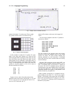
An 00E0 instruction erases the screen to all 0's. When the
CHIP-8 language is used, 256 bytes of RAM are displayed
on the screen as'an array of spots 64 wide by 32 high. A
white spot represents a I bit in RAM, while a dark (or off)
spot represents a 0 bit in RAM. Each spot position on th ' e
screen can be located by a pair of coordinates as shown in
Fig. 1.
The VX byte value specifies the number of horizontal
spot positions from the upper left corner of the display. The
VY byte value specifies the number of vertical spot
positions from the upper left corner of the display.
The DXYN instruction is used to show a pattern of spots
on the screen. Suppose we wanted to form the