


PR100 y 9
18. Install C1, a .01uF ceramic capacitor (marked 103, .01, or 10n).
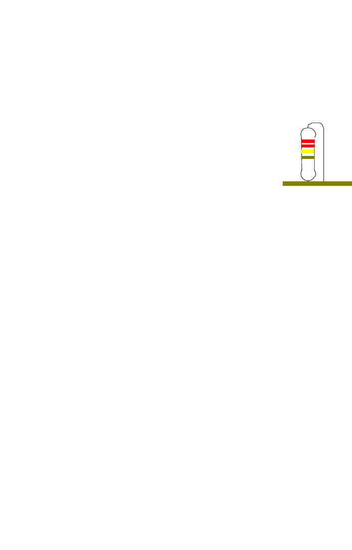
19. Install L2, another 2.2uH inductor (green body, red-red-gold stripes).
20. Install R3, a 18 ohm resistor (brown-grey-black).
21. Install C3, a .001uF capacitor (marked 102, or .001).
22. Install R5, a 300 ohm resistor (orange-black-brown).
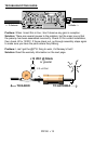
23. Install FL1, the two section helical filter. Make sure
and mount it firmly to the board, and that all leads are
soldered correctly.
At this point we will check all solder joints for possible cold
joints or even worse, solder bridges. Make sure everything
looks neat and clean before continuing, since the better it
looks, the easier it is to find problems.
24. If you have the appropriate F-connectors, install J3, otherwise leave
this part out so that you can solder your connecting cable straight to the
PC board.
Congratulations! You have completed assembly of your PR100. Before
continuing on to install your new preamp, check all of your solder joints
thoroughly, as well as part orientation. You definitely don’t want to seal this
into a weatherproof container before you verify if it works or not!