


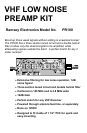
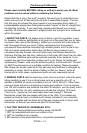

PR100 y 5
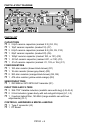
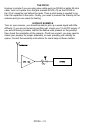
The RF passes through two more tank circuits consisting of L4 and C9 in the
second, and C12 and L5 in the third. Every time the RF goes through an
additional tank circuit, the bandpass bandwidth of the RF is narrower. The
narrower the bandwidth is before the active component of Q1, the better.
The narrow bandpass allows Q1 to devote its amplification to just the desired
signals. This means that it doesn’t amplify nearly as much noise, and won’t
amplify signals outside of the bandpass area. Q1 amplifies the RF up to a
respectable level, where it is sent out to FL1, the dual helical filter.
With steep cutoff frequencies and low loss, FL1 has very good bandpass
characteristics for our preamp. This filter is essentially a series of tank circuits
that have very high Q, and is designed with a specific frequency band in mind.
It is tuned by the user to be centered at 145 MHz with the two coils inside.
L2, L1, and C1 allows the DC fed through the coax line to pass on to Q1 to
power it, while rejecting the RF so that the unit does not self oscillate. C3
blocks the DC from coming into the filters, but allows the RF down to the cable.