


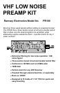

PR100 y 7
RAMSEY "LEARN-AS-YOU-BUILD ASSEMBLY STRATEGY"
We'll start building on the left side and work our way across, installing the lower
components up to the taller sized components. This will make our placing and
soldering of components easy.
Be sure to read through all of the steps, and check the boxes as you go to be
sure you didn't miss any important steps. Before you connect up the kit in a
hurry to see results, check all diodes, ICs, and capacitors for proper orientation.
Also check the board for any possible solder shorts or cold solder joints. All of
these mistakes could have detrimental effects on your kit - not to mention your
ego!
Kit building tips:
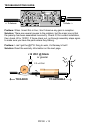
Use a good soldering technique - let your soldering iron tip gently heat the
traces to which you are soldering, heating both wires and pads simultaneously.
Apply the solder on the iron and the pad when the pad is hot enough to melt the
solder. The finished joint should look like a drop of water on paper, somewhat
soaked in.
Mount all parts on the top side of the board. This is the side that has no traces
or pads on it.
Part orientation - All parts in the kit are mounted at 90 degree angles to each
other, meaning that all parts are either parallel or perpendicular to the board.
Part installation - when parts are installed, the part is placed flat to the board,
and the leads are bent on the backside of the board to prevent the part from
falling out before soldering. The part is then soldered securely to the board, and
the remaining lead length is then clipped off. Since this is an RF project, make
sure that lead lengths are as short as possible, coming only second to
neatness.
In ALL PC board assembly steps, our word "INSTALL" means to do this:
• Insert the part, oriented or "pointed" correctly, into its holes in the PC
board.
• If helpful, gently BEND the part's wire leads or tabs to hold it into
place, with the body of the part snugly against the top side
("component side") of the circuit board.
• Solder ALL wires or pins of the part.
• Trim or "nip" all excess wire lengths extending beyond each solder
connection, taking care that wire trimmings do not become lodged in
solder connections.