


PR100 y 8
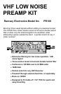
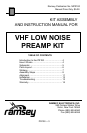
ASSEMBLY INSTRUCTIONS:
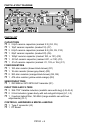
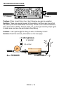
1. Orient the PC board as in the Parts Layout Diagram. We will start with
the left hand side of the board, then go to the right.
2. Install C6, the 22pF ceramic capacitor (marked 22).
3. Install C8, a 8.2pF ceramic capacitor (marked 8.2).
4. Install C4, a 2.2pF ceramic capacitor (marked 2.2).
5. Install C9, a 8.2pF ceramic capacitor (marked 8.2).
6. Install C5, another 2.2pF ceramic capacitor (marked 2.2).
7. Install C10, yet another 8.2pF ceramic capacitor (marked 8.2).
8. Install L3, one of the metallic, square shaped inductors (marked 359-
7787) Make sure the holes line up with the pins before soldering.
9. Install L4, another one of the inductors (marked 359-7787)
10. Install L5, the last of the tunable inductors (marked 359-7787).
11. Install C7, a 10pF ceramic capacitor (marked 10).
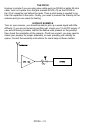
12. Install Q1, the 2SC2498 NPN UHF transistor. This transistor has
excellent low noise characteristics, and can amplify signals into the
microwave region! Note that the pin out of this transistor is different than
that of a switching transistor, so mount it in the orientation as shown in
the Parts Layout Diagram. Make sure and use the correct holes for
mounting!
13. Install R2, a 47K ohm resistor (yellow-violet-orange). Note that it is a
stand up part. Keep the leads as short as possible, as well as neat!
14. Install R1, a 100 ohm resistor (brown-black-brown). This is also a
stand up resistor as well. Bend your leads as shown in the diagram.
15. Install C2, a 100pF ceramic capacitor (marked 100 or 101).
16. Install L1, one of the 2.2uH coils (green body, red-red-gold stripes).
17. Install R4, a 300 ohm resistor (orange-black-brown). Notice that this
is a lay down part.