


PR100 y 4
INTRODUCTION TO THE PR100
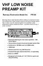
This amplifier is a truly necessary piece of equipment for your 2 meter receive
applications. With 16dB of gain, you mount this up on your mast on the antenna
to boost those weak signals to a receivable level. This results in clear,
unbroken reception, and a more pleasant listening experience.
The filtering of the preamplifier is narrow enough only to allow the desired
frequency band through, while rejecting all others. This prevents many
problems associated with interference such as intermodulation and front end
overload. Having such a narrow bandwidth also reduces background noise that
would normally be present in wider band amplifiers.
Hookup is very simple in that the unit is powered through the same cable that
you receive your signals through. It is possible to ‘feed’ the 12VDC up the coax
cable to the preamplifier. No new wires to run and makes for less
weatherproofing.
The PC board was designed to fit within a 1 1/2” PVC pipe, so a simple
enclosure could be created out of one piece of pipe and two endcaps. Glued
together it can make for the perfect weatherproof enclosure.
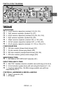
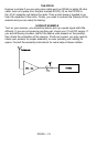
HOW IT WORKS
There really isn’t much to the preamplifier if you look to the schematic at the
right. It mostly consists of filtering, and has only one active part, Q1. We will
start from the Antenna end of the preamp, and then on to the receiver end.
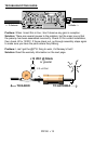
J1 and J2 is where the user can connect two different antennas. Some people
recommend that you use two turnstile antennas at right angles to each other for
good satellite imaging, if you’re using this with a weather satellite receiver. This
allows for good coverage of the horizons. Normally you will only use one of
these jacks.
From these jacks the unfiltered RF passes through C6, into the bandpass tank
circuit consisting of inductor L3 and capacitor C8. This tank circuit and the next
two are eventually tuned to be centered at 145 MHz. C4 allows some of the RF
from the first tank circuit to be allowed into the next, but is very small in
capacitance to offer a large reactance (resistance to AC). This high reactance
allows the tank circuits to perform their jobs better by giving them a higher Q
factor. This means that the spectrum of RF the tank circuits will allow through
becomes narrower due to the high Q.