


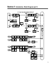
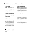

Section 1: Introduction- Physical Layout Diagram
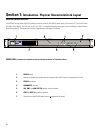
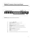
REAR PANEL (numbers correspond to reference locations shown above)
1- DataPort connectors PORT A - PORT H
2- PORT A CH 1 - PORT H CH 16 three-pin receptacles for audio inputs
3- PAGE three-pin receptacle for paging audio signal input
4- MONITOR CHAIN, IN and OUT five-pin receptacle for audio monitoring functions
5- RLY / TRG IN two-pin receptacle for remote sensing of switch closure or logic event
6- RLY OUT three-pin receptacle for output terminals of CM16a’s internal SPDT relay contacts
7- RCV, XMT and LINK STATUS network status indicators
8- 10BASE-T RJ-45 Ethernet computer network connection
9- RS-232 port for network and firmware utilities
10- IEC-type detachable AC power cord receptacle (for connection to AC line cord) with integral fuse holder
7