


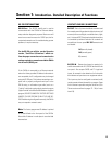

Section 2: Installation- Basics and Mounting
UNPACKING
There are no special unpacking precautions for the CM16a. Keep the original packing material for reuse in the rare event that service be
required on the CM16a. If service is required and the original packing material is not available, adequately protect for shipment (strong box
of appropriate size, sufficient packing material to prevent impact damage or load shifting).
WHAT IS INCLUDED IN THE CARTON
1- CM16a Amplifier Network Monitor
2- AC Power Cord
3- One complete set of the “Phoenix”-type connectors (18 pcs. of 3-pin style, 1 pc. of 5-pin style & 1 pc. of 2-pin style)
4- Hardware manual (this document)
LOCATION CONSIDERATIONS
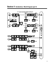
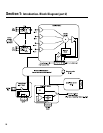
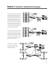
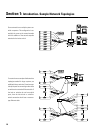
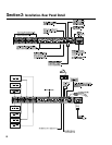
Where the CM16a is installed is dependent upon the location of audio input sources, amplifiers and network access. The system controller
computer should be located someplace convenient for the system operator. In most instances, the system controller computer is remote
from the CM16a and the amplifiers . It is preferable to install the CM16a and the amplifiers in the same or adjacent equipment racks; this
allows the cabling between them to be standard 15 pin VGA monitor cables. These cables are generally 2 meters long (6.5 feet). For longer
cabling runs, contact QSC’s Technical Services Department at (800) 772-2834 (toll free U.S.A. only) or (714) 957-7150. QSC offers a special
cable with individually-shielded twisted-pairs for each audio path; this cable can be used over distances as long as 100 meters (328 feet).
The maximum length of any 10BASE-T Ethernet network segment (cabling between any node and the next node, hub or repeater) is 100
meters (328 feet). The location of hubs and repeaters must be such that this distance limit is not exceeded. If this is impractical or impossible,
then use appropriate network transceivers and fiber optic cabling. For larger Ethernet networks, the use of Ethernet routers may be
necessary.
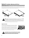
MOUNTING THE CM16a
Note- Rack mounting is optional.
The CM16a is secured to the front of the equipment rack with four screws and washers. Be sure to support the weight of the CM16a when
securing to avoid distorting or bending the front panel mounting ears. For mobile, touring or portable applications, support the rear of the
CM16a using the rear mounting tabs provided or contact QSC’s Technical Services Department to order rear rack ear extensions. The rear
rack ear extension kits add flexibility to you installation options as well as a support-pin option that requires one-time hardware installation
at the rear of the rack. For the locating dimensions of the rear support mounting tabs, see the dimensional diagram in the specification
section.
17