


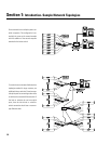

Section 1: Introduction- Detailed Description of Functions
AMPLIFIER MONITORING FUNCTIONS
Amplifier Model Detect- Identifies what model of
QSC amplifier is connected to the CM16a’s DataPort.
Amplifier Gain Detect- Reports the setting of the
amplifier’s gain setting (in dB) for each channel.
Bridge Mode Detect- Detects the position of the
bridge mode switch on each amplifier.
Clip Detect- Detects amplifier clipping on each chan-
nel.
Headroom Metering- Reports the “available” re-
maining signal level that the input signal can be driven
before clipping will occur.
Heat Sink Temperature Metering- Monitors the
heatsink temperature of each channel of each amplifier
connected to the CM16a. If the temperature exceeds a
user specified value (in software) then the Over-Temp.
“object” will alert the system operator.
Load Monitor Detect- Monitors the impedance of
the load at the amplifier output for each channel.
Output Current Meter- Provides for metering of the
amplifier’s output current on each channel.
Output Voltage Meter- Provides for metering of the
amplifier’s output voltage on each channel.
Output Open Detect- Detects when the load con-
nected to the amplifier is above a user specified value
in software.
Output Short Detect- Detects when the amplifier
load is below a user specified value in software.
Power Status Detect- Reports AC power status of
the amplifier (ON/standby/ OFF).
Protect Status Detect- Reports if the amplifier has
entered “protect” mode (such as thermal, over-current
or power-up muting protect status).
Real Power Detect- Reports the “real” power the
amplifier is delivering. This “real” power is not the
same as “reactive” power. Real power is the product of
current and voltage times the cosine of the phase angle
between them.
Threshold Adjust- This indicates that the behavior of
the associated block requires the input of a threshold
value in software that must be crossed for the detection
to occur. This allows the system operator to tailor the
behavior of the system to each application.
PAGING FUNCTIONS
Input Sensitivity- Sets the sensitivity of the Page
Input to either 1 Vrms or 3 Vrms. This selection should
coincide with the level of the audio signal provided for
the Page Input.
DAC- This is a digital-to-analog converter that takes
digital information from the internal microcontroller
and outputs the corresponding analog “equivalent” to
the appropriate channel PAGE insert points . This oc-
curs only by instructions issued by the system operator
or a custom control application.
Page Input- This is a 3-pin terminal block connector
used for balanced line level page audio-signal input.
12