20
How to Interpret the Graphs (Continued)
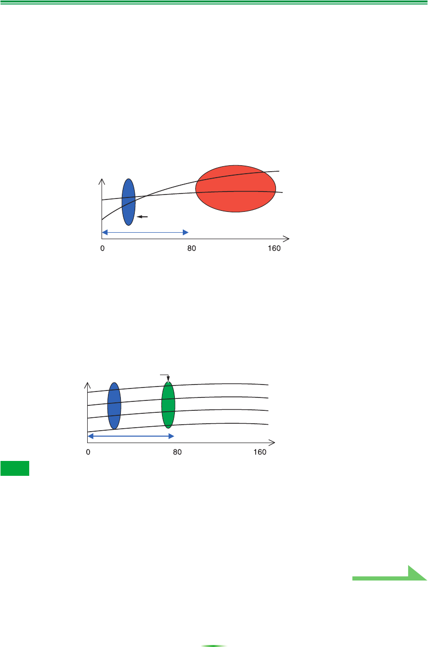
Pattern 2: Different reverb characteristics for different channels
If the reverb characteristics differ for the different channels as shown in Figure 3, equalization using the
conventional Acoustic Cal EQ acquired data between 80 and 160 [ms] (red part of Figure 3), so equalization
was performed to gradually equalize the tone of the different channels for 80 ms from the time the sound
was emitted from the speakers and after (it was not possible to equalize the response of the direct sound).
However, the sense of placement and movement of the acoustic image and the unity of the sound from the
different speakers is influenced not by the reverberations but by the direct sound from the speakers
(including the early reflected sound). In cases like this, you should use Advanced EQ Setup and set the
time period to 30 to 50 msec (the blue area in Figure 3). This allows the characteristics of direct sounds
to be balanced for each channel, giving an ideal sound field with good acoustic positioning and
movement.
Figure 3
Pattern 3: Similar reverb characteristics for high and low frequencies and
all channels
As shown in Figure 4, when the reverb characteristics for all channels are similar across all frequencies,
your sound experience will probably not be adversely affected by reverberation. We recommend
calibrating with a time of about 60 to 80 [ms] (green part of Figure 4) specified at Advanced EQ Setup.
This produces a total calibration for both direct sounds and reverberations, resulting in an ideal sound
field.
Figure 4
• If you are not sure which time period to specify in Advanced EQ Setup, start by trying 30 to 50 msec. If the
graphs show an unusual reverb curve for a specific frequency, the cause may be some accidental
variation. Instead of selecting 30 to 50 msec, try another time period.
• Another good method is to try various time periods in Advanced EQ Setup and select the one which
sounds the best.
• Time period settings cannot be made on the PC. They can only be made on the GUI screen output from
the receiver’s video outputs, using the receiver’s Advanced EQ Setup function.
Note
Level
(dB)
Time period
point to be
selected
Time (in ms)
Front left channel
Front right channel
Level
(dB)
Time (in ms)
Front left low frequencies
Front right low frequencies
Front left high frequencies
Front right high frequencies
Time period point to
be selected
Continue


