


Connecting your equipment
03
31
En
Making MULTI-ZONE connections
It is possible to make these connections if you have a
separate TV and speakers for your primary (
ZONE 2
) sub
zone, and a separate amplifier (and speakers) for your
secondary (
ZONE 3
) sub zone. You will also need a separate
amplifier if you are not using the
MULTI-ZONE setup using
speaker terminals (ZONE 2)
below for your primary sub
zone. There are two primary sub zone setups possible with
this system. Choose whichever works best for you.
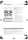
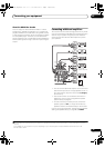
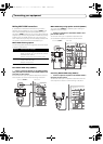
MULTI-ZONE listening options
The following table shows the signals that can be output
to ZONE 2 and ZONE 3:
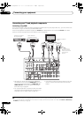
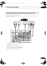
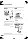
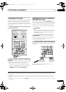
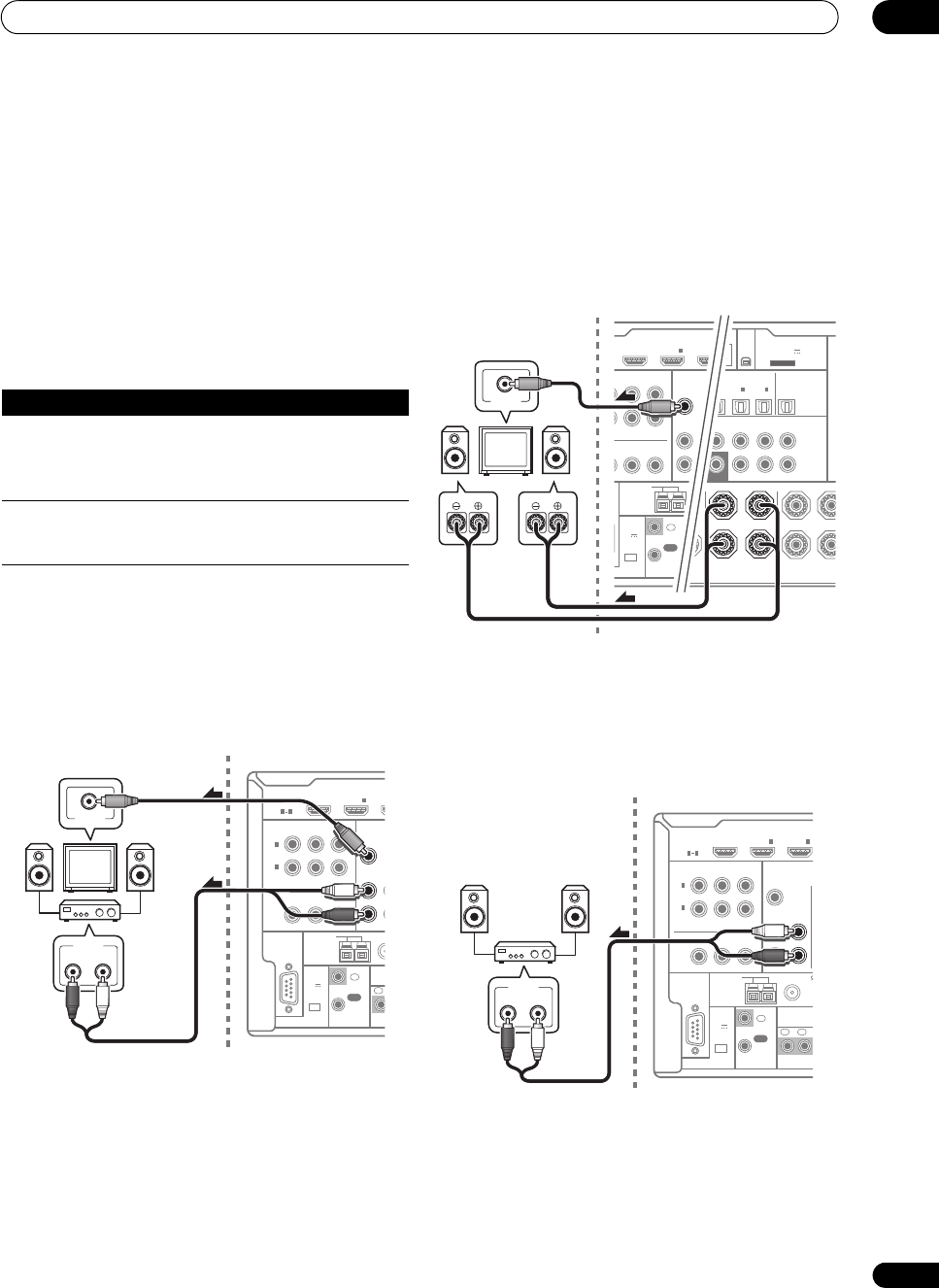
Basic MULTI-ZONE setup (ZONE 2)
• Connect a separate amplifier to the
AUDIO ZONE 2
OUT
jacks and a TV monitor to the
VIDEO ZONE 2 OUT
jack, both on this receiver.
You should have a pair of speakers attached to the sub
zone amplifier as shown in the following illustration.
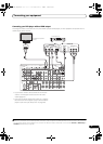
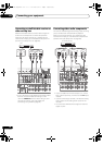
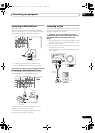
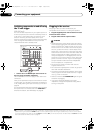
MULTI-ZONE setup using speaker terminals (ZONE 2)
You must select ZONE 2 in Speaker system setting on
page 83 to use this setup.
• Connect a TV monitor to the
VIDEO ZONE 2 OUT
jacks on this receiver.
You should have a pair of speakers attached to the
surround back speaker terminals as shown below.
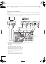
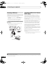
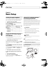
Secondary MULTI-ZONE setup (ZONE 3)
• Connect a separate amplifier to the
AUDIO ZONE 3
OUT
jacks on this receiver.
You should have a pair of speakers attached to the sub
zone amplifier as shown in the following illustration.
Sub Zone Input functions available
ZONE 2 DVD, TV/SAT, DVR/BDR, VIDEO, INTERNET
RADIO, iPod/USB, XM
a
, CD, CD-R/TAPE, TUNER,
ADAPTER PORT, SIRIUS
(Outputs analog audio and composite video.)
a.VSX-1325 only.
ZONE 3 DVD, TV/SAT, DVR/BDR, VIDEO, CD, CD-R/TAPE,
TUNER, ADAPTER PORT
(Outputs analog audio.)
RS-232C
HDMI
ASSIGNABLE
COMPONENT VIDEO
ASSIGNABLE
MONITOR
OUT
IN
Y
P
R
Y
ANTENNA
FM
U
AM LOOP
ZONE2
OUT
Z
P
B
P
R
P
B
1
INBD
IN
1
1 4
(
DVD
)
IN
2
(
DVR/BDR
)
CONTROL
EXTENSION
1
2
IN
IN
OUT
1
(
O
TO
(
OUTPUT
5 V
150 mA
MAX
)
RL
AUDIO IN
VIDEO IN
Main zoneSub zone (ZONE 2)
OPTICAL
ASSIGNABLE
L R L(Single)
SURROUND BACK
R
R
L
FRONT HEIGHT / FRONT W
IN
1
(
TV/SAT
)
IN
2
(
DVR /B DR
)
IN
OUT
FRONT CENTER SURROUND SURR BACK
(Single)
FH/FW
3
(
VIDEO
)
IN
2
(
CD
)
SUBWOOFER
0/100
)
(
OUTPUT 5 V
100 mA MAX
)
ADAPTER PORT
PRE OUT
XM
IN
C
E
NT VIDEO
ASSIGNABLE
P
R
ANTENNA
FM UNBAL AM LOOP
ZONE2
OUT
ZONE3
OUT
P
B
P
R
P
B
INBD
IN
1
CONTROL
XTENSION
IR
12 V T
IN
IN IN
OUT
1
(OUTPU
TOTAL 1
(
OUTPUT
5 V
150 mA
MAX
)
VIDEO IN
RL
Main zone
Sub zone (ZONE 2)
RS-232C
HDMI
ASSIGNABLE
COMPONENT VIDEO
ASSIGNABLE
MONITOR
OUT
IN
Y
P
R
Y
ANTENNA
FM UNBAL 75 AM LOOP
ZONE2
OUT
ZONE3
OUT
P
B
P
R
P
B
1
INBD
IN
1
IN
2
1 4
(
DVD
)
IN
2
(
DVR/BDR
)
CONTROL
EXTENSION
IR
12 V TRI
G
IN
IN IN
OUT
12
(OUTPUT 1
2
TOTAL 150
m
(
OUTPUT
5 V
150 mA
MAX
)
RL
AUDIO IN
Main zone
Sub zone (ZONE 3)
VSX-1325_UXJCB.book 31 ページ 2010年3月9日 火曜日 午後3時4分