


TDA8559_3 © Koninklijke Philips Electronics N.V. 2006. All rights reserved.
Product data sheets Rev. 03 — 15 May 2006 22 of 36
Philips Semiconductors
TDA8559T
Low-voltage stereo headphone amplifier
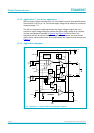
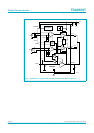
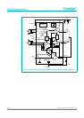
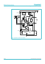
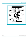
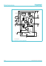
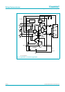
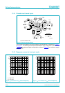
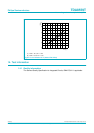
13.14 Printed-circuit board layout
The Printed-Circuit Board (PCB) layout supports all applications as illustrated in Figure 8
to Figure 14. The PCB layout has been assembled for input configuration as shown in
Figure 3, and output and supply configuration as shown in Figure 8 for a maximum supply
voltage of 6 V.
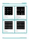
13.15 Response curves for low input mode
Top view component side.
Fig 15. Printed-circuit board layout
001aae801
100 µF
22 µF
220 µF
220 µF
MUTE
TDA8559T
INP2
Out2
Out1
D&A AUDIO POWER
QC - NIJMEGEN
HR
TDA8559T
Buf.
INP1
+Vp
Std.
by
220 nF
5.1 kΩ
Inp.
mode
1
89
220 nF
100 nF
5.1 kΩ
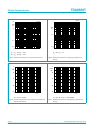
(1) High mode.
(2) Low mode.
Fig 16. I
q
as a function of V
P
(stereo headphone) Fig 17. V
P1
as a function of V
P2
(stereo headphone)
020
10
0
2
4
6
8
I
q
(mA)
48
V
P
(V)
12 16
mda089
(2)
(1)
20
010 30
0
20
4
8
V
P1
(V)
V
P2
(V)
12
16
mda090