


TDA8559_3 © Koninklijke Philips Electronics N.V. 2006. All rights reserved.
Product data sheets Rev. 03 — 15 May 2006 15 of 36
Philips Semiconductors
TDA8559T
Low-voltage stereo headphone amplifier
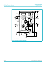
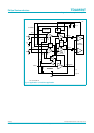
13.12 Application 7: Line driver application
With the supply voltage connected to pin 15 it is possible to use the head amplifier above
the maximum of 18 V to pin 16. The internal supply voltage will be reduced to a maximum
of approximately 17 V.
This will be convenient in applications where the supply voltage is higher than 18 V,
however an output voltage swing that reaches the higher supply voltage is not required.
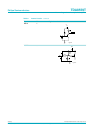
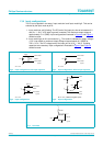
the input configurations illustrated in Figure 5 and Figure 6 should be used. This
application can also be used for headphone applications. However, due to the limited
output current, series resistors have to be used between the output pins and the load; see
Figure 14.
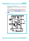
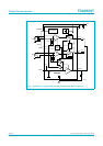
13.13 Application diagrams
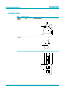
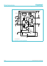
Fig 8. Application 1; single-ended with loudspeaker capacitor
+
−
+
−
+
−
+
−
OA
INPUT
LOGIC
V/I
REFERENCE
V/I
1
STANDBY
MUTE
MODE
SVRR
GND
2
3
5
6
4
12
Cb
BUFFER
OUT2
OUT1
IN1
IN2
mgd116
11
14
1615
13
7
8
V
P
V
P
V
P1
V
P2
BUFFER
OA
50 kΩ
100 kΩ
100
kΩ
50 kΩ
50 kΩ
50 kΩ
50
kΩ
50
kΩ
TDA8559T
DQC
100 µF
220 µF
220 µF
100
nF
+V
P
32 Ω
32 Ω
+−
+−
22 µF
Cr