


TDA8559_3 © Koninklijke Philips Electronics N.V. 2006. All rights reserved.
Product data sheets Rev. 03 — 15 May 2006 10 of 36
Philips Semiconductors
TDA8559T
Low-voltage stereo headphone amplifier
10. Limiting values
11. Thermal characteristics
12. Characteristics
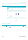
Table 5. Limiting values
In accordance with the Absolute Maximum Rating System (IEC 60134).
Symbol Parameter Conditions Min Max Unit
V
P2(max)
maximum supply voltage (pin 15) - 30 V
V
P1(max)
maximum supply voltage (pin 16) - 18 V
V
i(max)
maximum input voltage - 18 V
I
ORM
peak output current repetitive - 150 mA
P
tot
total power dissipation - 1.19 W
T
amb
ambient temperature −40 +85 °C
T
stg
storage temperature −55 +150 °C
T
vj
virtual junction temperature - 150 °C
t
sc
short-circuiting time V
P
<10V - 1 h
Table 6. Thermal characteristics
Symbol Parameter Conditions Typ Unit
R
th(j-a)
thermal resistance from junction to ambient in free air 105
K/W
Table 7. Characteristics
V
P
= 3 V; T
amb
= 25
°
C; f
i
= 1 kHz; unless otherwise specified.
Symbol Parameter Conditions Min Typ Max Unit
DC characteristics
V
P
operating supply voltage
[1]
1.9 3 30 V
I
q(tot)
total quiescent current open load - 2.75 4 mA
I
stb
standby supply current open load - - 10 µA
V
1
Standby mode voltage standby 0 - 0.5 V
operating 1.5 - 18 V
V
7
Mute mode voltage mute 0 - 0.5 V
operating 1.5 - 18 V
I
bias
input bias current - 100 300 nA
Single-ended stereo application (R
L
= 32 Ω)
P
o
output power THD = 10 % 30 35 - mW
THD total harmonic distortion P
o
= 20 mW; f
i
= 1 kHz
[2]
- 0.075 0.15 %
P
o
= 20 mW; f
i
=10kHz
[2]
- 0.1 - %
G
v
voltage gain 25 26 27 dB
f
ss
small signal roll-off
frequency
−1 dB - 750 - kHz
α
cs
channel separation R
s
= 5 kΩ 40--dB
∆G
v
channel unbalance - - 1 dB