


TDA8559_3 © Koninklijke Philips Electronics N.V. 2006. All rights reserved.
Product data sheets Rev. 03 — 15 May 2006 12 of 36
Philips Semiconductors
TDA8559T
Low-voltage stereo headphone amplifier
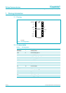
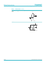
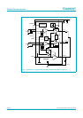
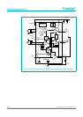
The capacitor Cb is recommended for stability improvement. The value may vary between
10 nF and 100 nF. This capacitor should be placed close to the IC between pin 12 and
pin 13.
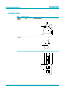
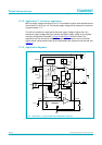
13.2 Heatsink design
The standard application is stereo headphone single-ended with a 32 Ω load impedance
to buffer (see Figure 9). The headphone amplifier can deliver a peak output current of
150 mA into the load.
For the SO16 envelope R
th(j-a)
= 105 K/W; the maximum sinewave power dissipation for
T
amb
=25°C is:
For T
amb
=60°C the maximum total power dissipation is:
13.3 Test conditions
T
amb
=25°C; unless otherwise specified: V
P
= 3 V, f = 1 kHz, R
L
=32Ω, Gain = 26 dB,
low input mode, band-pass filter: 22 Hz to 30 kHz. The total harmonic distortion as a
function of frequency was measured with low-pass filter of 80 kHz. The quiescent current
has been measured without any load impedance.
In applications with coupling capacitors towards the load, an electrolytic capacitor has to
be connected to pin 4 (SVRR).
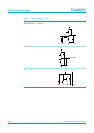
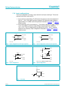
1. The graphs for the single-ended application have been measured with the application
illustrated in Figure 9; input configuration for input mode low (Figure 4) and input
configuration for input mode high (Figure 6).
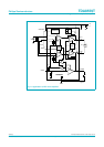
2. The graphs for the BTL application ‘input mode low’ have been measured with the
application circuit illustrated in Figure 11 and the input configuration illustrated in
Figure 4.
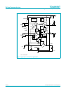
3. The graphs for the line-driver application have been measured with the application
circuit illustrated in Figure 13 and the input configuration illustrated in Figure 6; input
mode high.
1.2 W
150 25–
105
---------------------
=
0.85 W
150 60–
105
---------------------
=