


TDA8559_3 © Koninklijke Philips Electronics N.V. 2006. All rights reserved.
Product data sheets Rev. 03 — 15 May 2006 13 of 36
Philips Semiconductors
TDA8559T
Low-voltage stereo headphone amplifier
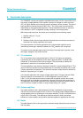
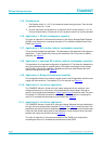
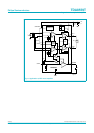
13.4 Input configurations
The IC can be applied in two ways, ‘input mode low’ and ‘input mode high’. This can be
selected by the input mode at pin 8:
1. Input mode low: pin 8 floating: The DC level of the input pins has to be between 0 V
and (V
P
− 1.8 V). A DC path to ground is needed. The maximum output voltage is
approximately 2.1 V (RMS). Input configurations illustrated in Figure 3 and Figure 4
should be used.
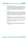
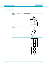
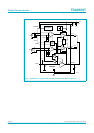
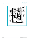
2. Input mode high: pin 8 is connected to V
P
: This mode is intended for supply voltages
> 6 V. It can deliver a maximum output voltage of approximately 6 V (RMS) at
THD = 0.5 %. The DC voltage level of the input pins is (0.5V
P
+ 0.6 V). Coupling
capacitors are necessary. Input configurations illustrated in Figure 5 and Figure 6
should be used.
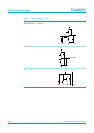
V
P
< 6 V. V
P
< 6 V.
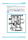
Fig 3. Input configuration; with input capacitor Fig 4. Input configuration; without input capacitor
2.2 µF
V
IN
mgd123
5 kΩ INPUT
pins 2 and 5
pins 3 and 6
V
IN
mgd124
INPUT
pins 2 and 5
pins 3 and 6
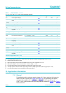
V
P
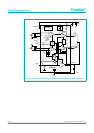
< 6 V. At V
P
< 6 V, combined negative inputs.
Fig 5. Input configuration Fig 6. Input configuration
220 nF
V
IN
mgd125
220 nF
INPUT
pins 2 and 5
pins 3 and 6
220
nF
100 nF
100 nF
V
IN
V
IN
mgd126
pin 2
pin 3
pin 6
pin 5
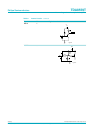
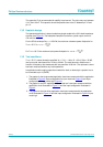
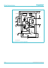
Fig 7. Soft mute
V
P
7
mute
620 kΩ
47 kΩ
220 nF
mgl135