


9397 750 13928 © Koninklijke Philips Electronics N.V. 2004. All rights reserved.
Product data Rev. 03 – 23 August 2004 21 of 31
Philips Semiconductors
PNX2000
Audio video input processor
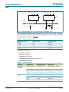
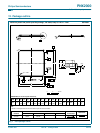
[1] Allowed SCK/WS ratios are 32, 48, 64, 128 and 256 SCK periods per WS period.
[2] All timings relative to the rising edge of SCK.
[3] See Section 10.4
for waveforms.
t
h(DATA)
data hold at Rx 40 pF load - - 4.9 ns
I
2
S
f
s
audio sample frequency - 32 48 48 kHz
f
SCK
SCK frequency I
2
S-bus master mode - 64f
s
--
f
SCK
SCK frequency I
2
S-bus slave mode 32f
s
64f
s
256f
s
-
DF
SCK
SCK duty factor I
2
S-bus master mode 40 50 60 %
DF
SCK
SCK duty factor I
2
S-bus slave mode 35 - 65 %
t
RSCK
SCK rise / fall time I
2
S-bus master mode; C
load
= 30 pF - - 5 ns
t
RSCK
SCK rise / fall time I
2
S-bus slave mode; f
SCK
= 3.072 MHz - - 50 ns
t
d
delay time: SCK to WS and SD
outputs
[2]
T
SCK
= 1/f
SCK
0.3 0.5 0.7 T
SCK
t
h
hold time: SCK to WS and SD inputs - 0 - - ns
t
s
setup time: WS and SD inputs to
SCK
T
SCK
= 1/f
SCK
0.2 - - T
SCK
I
2
D
f
clock(WORD)
word clock frequency - - 13.5 - MHz
WL word length - - 44 - bit
DR data rate - - 594 - Mbit/s
f
clock(BIT)
bit clock freq. - - 297 - MHz
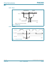
JTAG Clock Reset
t
low
Time RESET_N should be below
V
trip_high
before internal reset = 1.
RESET_SEL = 0 - - 11 µs
t
high
Time RESET_N should be above
V
trip_high
before internal reset = 0
(after t
pulse
).
RESET_SEL = 0 - - 2 µs
t
pulse
Time before PNX2000 internal reset
= 0
[3]
.
RESET_SEL = 0 200 - - ns
Table 23: Dynamic characteristics
…continued
Symbol Parameter Conditions Min Typ Max Unit