


9397 750 13928 © Koninklijke Philips Electronics N.V. 2004. All rights reserved.
Product data Rev. 03 – 23 August 2004 16 of 31
Philips Semiconductors
PNX2000
Audio video input processor
• Serial data link interfacing for analog multi-purpose interface PNX3000.
8. Television application
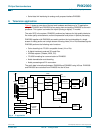
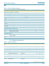
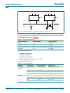
Figure 3 shows an overview of the top level hardware architecture of a TV application,
using the PNX3000 and PNX2000 as an analog front-end and the PNX8550 as the main
processor. This system is aimed at the hybrid (analog or digital) TV market.
The main SOC in the system, PNX8550, performs key features for high quality television
like video quality enhancement, motion compensation and picture-in-picture processing.
PNX2000 together with PNX3000 are used to perform the input decoding of a single
stream of analog audio and a single stream of analog video (1f
H
or 2f
H
) broadcast signals.
PNX2000 performs the following main functions:
• Color decoding into ITU-601 compatible format (1f
H
or 2f
H
).
• A digital interface to external 3D comb filter.
• VBI data capture (Teletext, WSS, CC).
• ITU-656 formatting for communication to PNX8550.
• Audio demodulation and decoding.
• Audio processing and D-A conversion.
The audio data is transferred between PNX2000 and PNX8550 using I
2
S-bus. PNX2000
and PNX3000 are controlled from PNX8550 via the I
2
C-bus.
Fig 3. TV application
mce558
PNX8550
YUV (656)
CVBS
audio I
2
S-bus
audio I
2
S-bus
(2×)
RGB
10 bits (3×)
32-bit
8-bit or 16-bit
audio I
2
S-bus
(3×)
DISPLAY
PROCESSOR
RGB
AMPLIFIER
DEFL.
CONT.
AUDIO
AMPLIFIER
PNX2000
PNX3000
STANDBY
MICRO-
CONTROLLER
TUNERS
UV1316
UV13361
LEVEL ADJUSTMENT
REMOTE CONTROL
LOCAL KEYPAD
I
2
D
SIF
status
SCART
VIF
CVBS Y/C
RGB 2
L/R audio 2
CVBS 1
L/R audio 1
L/R
audio
DDR
16 Mb
FLASH
ROM
18 Mb
2
4
6
8
10
12
14
11
13
16
18
15
17
19
20
21
2
4
6
8
10
12
14
11
9
7
5
3
1
13
16
18
15
17
19
20
21