Balanced and Unbalanced Input Lines
Recording and broadcast studios use balanced
connections almost exclusively because of their
inherent ability to reject noise and hum, assuring the
best sound. Certain high quality preamplifiers and
surround controllers built for residential use utilize
balanced connections with XLR jacks for the same
reasons. The P 3’s balanced outputs enable you to
take full advantage of the inherent noise rejection
capability and superior sound quality of Parasound
Halo power amplifiers.
Unbalanced connections with RCA jacks are found on
all home audio equipment. RCA jacks and two-
conductor wires are less costly than the additional
circuitry, higher priced XLR connectors and three-
conductor wiring required for balanced connections.
In an unbalanced line, the positive audio signal
appears at the center pin of the RCA jack and the
negative signal on the outer shield wire, which also
functions as the ground connection. Unbalanced
interconnect cables are vulnerable to hum from an AC
line, or other noise, such as RFI (Radio Frequency
Interference), which can be reproduced through your
loudspeakers. Since the unbalanced line’s ground
also carries the audio signal, there is no way for the
connected amplifier or preamplifier to distinguish
between the audio signals you want and unwanted
noise emanating from external sources.
Balanced lines are superior because they utilize
separate conductors for audio and ground: two inner
conductors carry the positive and negative audio
signal, and a third outer wire connects the grounds
and also shields the two signal conductors. When the
positive and negative signals appear at the
component receiving the signal they are equal, but
180 degrees out of phase with each other with respect
to ground. To send and receive balanced signals
requires special differential circuitry.
A differential input circuit amplifies only the
difference between the positive and negative signals.
For example, when a 1 Volt signal arrives at a
balanced input stage, the differential input “sees” a
positive 1 Volt minus a negative 1 Volt, or 2 Volts total.
External hum and noise that somehow get into a
balanced line is common to both its positive and
negative conductors with respect to ground.
Therefore, it’s canceled, or rejected, by the differential
input circuit.
This phenomenon of rejecting noise signals common to
both positive and negative conductors is called
common-mode rejection. Differential inputs are
specified according to how well they reject signals
common to both conductors. This is measured in dB and
is called the common mode rejection ratio or CMRR.
TECHNICALLY SPEAKING
Direct Inputs
The P 3 direct inputs have the shortest signal paths
with the fewest parts from the input to the output to
avoid any contamination from collateral tone control
or record output circuits. As a result, you can’t alter
tone or make recordings from components that are
connected to Direct Inputs 1 or 2.
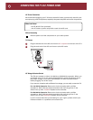
External Loop In / Out Connections
The left and right channel External Loop In/Out jacks
come from the factory with jumpers installed. When
these jumpers are removed, you can "insert" signal-
processing components into the internal signal path
of the P 3. This includes signal processors such as
surround decoders, equalizers, and spatial
enhancers. The External Loop also lets you patch in a
second audio record/playback system such as
computer-based CD-R, CD-RW, and MP 3 burning and
monitoring components. You can also use the
External Loop to add in sound effects, narration, or
music on videotaped movies.
Output Connections
There are two pairs of output jacks on the rear panel
of your P 3, one balanced pair and one unbalanced
pair. When a source is playing, both outputs are
active. You can connect both output pairs
simultaneously to two amplifiers if you wish.
Balance
You can change the balance a maximum of 12 dB in
either direction. Usually, you should not need to
change the balance level from its 0 dB middle
position, but if your listening area is closer to one
speaker or the other, you can compensate for this
with the balance control so one speaker does not
sound louder than the other does.
Balanced Output Connections
Use the balanced output to connect your P 3 to a
power amplifier with balanced inputs such as the
Parasound Halo Series amplifiers. Like the Balanced
Inputs, the Direct Balanced XLR inputs provide the
highest-quality audio transmission of the P 3's
outputs. As mentioned earlier, balanced circuits
provide superior hum and noise cancellation and can
even eliminate hum created by ground loops,
especially in long wire runs.
Bass and Treble Level Controls and Tone Button
The bass and treble controls offer adjustment of
overall tonal balance. The Bass controls allow you to
boost or cut low frequencies +/- 10 dB in 2 dB steps.
The Treble controls allow you to boost or cut high
frequencies +/- 10 dB in 2 dB steps. To preserve sonic
clarity, use these controls sparingly and only for
recordings that sound better with them. You will find
that very slight adjustments can add a degree of
warmth, richness, clarity and airiness. However,
greater adjustments may obscure musical detail, and
22


