


3-16 ChartScan User’s Manual
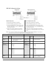
Digital Filtering:
• Averages 32 samples at 50/60 Hz for line cycle noise rejection (VDC measurements)
Voltage Range
2
, Accuracy
3
and Resolution:
• ±100 mV ± 0.02% 3.05 µV/bit
• ±1 V ± 0.02% 30.5 µV/bit
• ±5 V ± 0.02% 153 µV/bit
• ±10 V ± 0.02% 306 µV/bit
Note 1: Accuracy is based on 18 to 28°C, 1 year; includes cold junction compensation; excludes thermocouple errors;
thermocouple readings based on NIST Monograph 175. Resolution given is the typical value. Add ±5°C for common
mode voltages greater than 25 VAC.
Note 2: Voltage range is maximum peak-to-peak signal for AC volts.
Note 3: For AC voltages where the frequency of the input signal is an integer multiple of the AC line cycle ±1%; with line cycle
integration enabled.
Note 4: Specified for coupling impedance >30 MΩ and common mode frequency < 60 Hz. 300 VDC or 300 VAC peak before
equipment damage occurs.
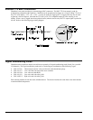
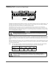
Note 5: There is a 4700 pico-farad, polypropylene capacitor connected across the input terminals of each channel. This
capacitor filters input noise when measuring signals from thermocouples. When the circuit card is set to the ±100 mV
range, the capacitor reacts with user source impedance to form a low pass filter. The filter pole frequency is:
1/(2*pi*(RSHI + RSLO)*4700 * 10
-12
), where RSHI and RSLO are the source resistance of the input leads.