


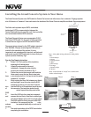
Installing the Grand Concerto System in Your Home
I. Prewire
The Grand Concerto System uses CAT5 cable for Control Pad control and either two or four-conductor 16-gauge speaker
wire. All the wire is “homerun” from each zone to the location of the Grand Concerto amplifier and Audio Source equipment.
Complete CAT5 Crimping Instructions
The NuVo audio systems require CAT5, unshielded,
twisted pair (UTP) for communication between the
Control Pads and the main amplifier unit. Each end of the
wire is terminated with an RJ45 connector.
The Grand Concerto System can accommodate 2,000
total feet of CAT5 cable. For the most reliable operation,
it is best that no single run of CAT5 exceeds 250 feet.
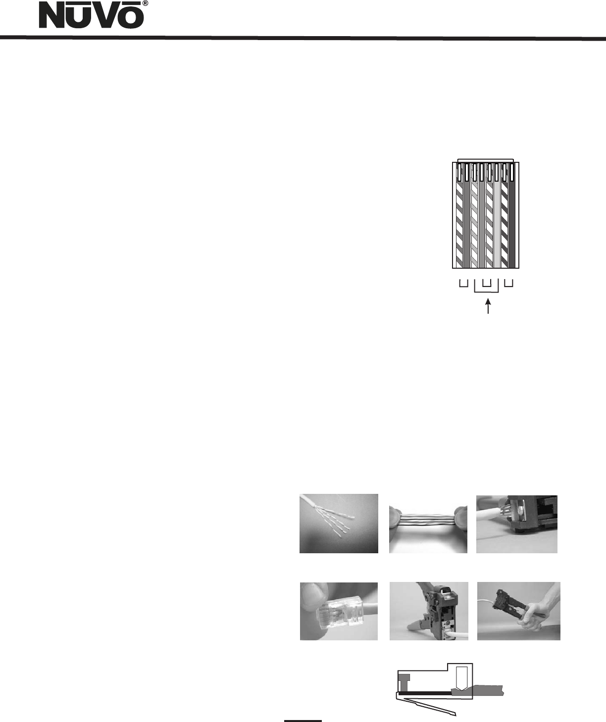
The correct wiring scheme for the CAT5 cable is standard
EIA/TIA 568A. Properly terminating the CAT5 cable is
crucial for the operation of the system. It is very
important to use a good quality crimp tool, and test each
end to end run with a CAT5 wire tester to insure that your
system operates flawlessly, Fig.1.
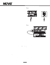
Step-by-Step Crimping Instructions:
1. Strip a 2 to 3 inch portion of the insulation,
exposing the 4 twisted pairs.
2. Untwist the wires and fan them out
individually. Arrange the wires into the
correct color scheme as shown in Fig. 1.
3. Flatten the wires in their correct order and trim
them evenly across the top. Most crimp tools
have a wire trimmer built-in. It is best to trim the wires
to about ½” in length.
4. While holding the wires flat between your thumb
and forefinger, insert the wires into the RJ45
connector so each is in its own slot. Push the
wire into the RJ45 so all 8 conductors touch the end
of the connector. The insulation jacket should
extend beyond the crimp point of the
RJ45.
5. Insert the RJ45 into the crimp tool receptacle
and squeeze the tool firmly. Note that a ratchet type
tool should tighten down until it no longer clicks.
6. The RJ45 should be firmly crimped to the CAT5
insulation. It is necessary that the color
scheme be repeated identically on each end of
the wire.
7. Test each termination with a CAT5 Tester before
completing the installation.
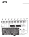
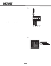
Fig. 1: EIA 568A wiring scheme for CAT5 Cable
Pin #
1. Green Stripe
2. Green
3. Orange Stripe
4. Blue
5. Blue Stripe
6. Orange
7. Brown Stripe
8. Brown
Note: Colors listed as “stripe” are a white wire
with a colored stripe.
Step 1 Step 2 Step 3
Step 4
Step 5 Step 6
1 2 3 4 5 6 7 8
Top view with
tab down.
Wires insert from
this end.
Pair 2
Pair 3
Pair 4
Pair 1
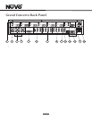
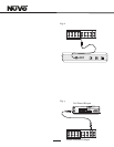
IR
Ac
t
i
ve
G
r
ou
nd
Cont
r
o
l
Da
t
a
B
u
s
-
C
on
t
r
o
l
D
a
t
a B
u
s
+
IR
Dat
a
Gr
o
u
n
d
+
24V
P
ower
G
r
ou
n
d
7