


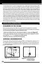
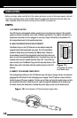
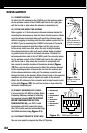
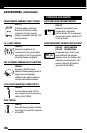
Figure 19.
Vertical alignment of
antenna is necessary
for optimal reception
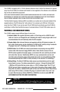
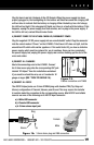
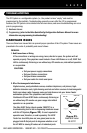
Figure 20.
Antenna connection
to “L” Bracket
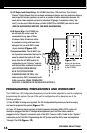
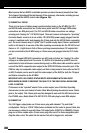
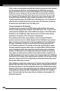
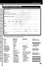
1 = GREEN/WHITE
2 = GREEN
3 = ORANGE/WHITE
4 = BLUE
5 = BLUE/WHITE
6 = ORANGE
7 = BROWN/WHITE
8 = BROWN
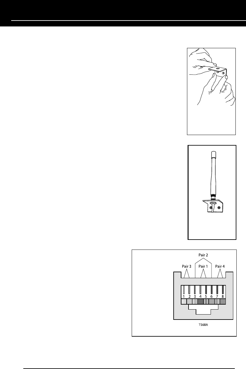
Figure 21. T568A wire termination
INSTALLATION
11) CONNECT ANTENNA
To attach the RF antenna to the HT-MSU, push the antenna down
on the antenna socket of the HT-MSU and twist to the right (you
will feel a click or stop when the antenna is completely on).
12) EXTEND AND MOUNT THE ANTENNA
Niles supplies a 10 foot extension cable and antenna bracket for
mounting the antenna away from the home theater sources. Make
sure the antenna extension cable will reach the antenna mount
without snagging or twisting with the other cables needed for the
HT-MSU. If you’re mounting the HT-MSU to the back of the metal
professional equipment rack that slides-out (for easy access
to the wires), make sure that, when the rack is fully extended,
the antenna extension cable will reach without being stretched
or pinched when the rack is slid back into place. To attach the
antenna extension cable to the HT-MSU, push the connector down
on the antenna socket of the HT-MSU and twist to the right (you
will feel a click or stop when the connector is completely on).
Use a pencil to mark the location of the antenna bracket. (Figure
19) Then, use two dry-wall screws to attach the antenna bracket
to the mounting surface. Unscrew the nut from the antenna end
of the antenna extension cable; put the antenna connector end
through the hole in the bracket. Attach the nut back on the antenna
connector end of the cable to tighten the cable to the bracket.
Attach the RF antenna to the connector/wall bracket combo; twist
to the right (Figure 20). You will feel a click or stop when the
antenna is completely on.
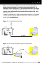
13) CONNECT EXPANSION CAT-5 CABLE
If connecting the HT-MSU to a Niles Radio
Frequency Gateway instead of attaching
the supplied antenna (SEE THE SYSTEM
DESIGN CONSIDERATION SECTION,
CONFIGURATION #3), use CAT-5 cable
terminated with RJ45 connection plugs.
The CAT-5 cable must be terminated using
the T568A standard wiring (Figure 21).
14) RE-CONNECT POWER TO THE HT-MSU
You are now ready to program the Niles iC2 System.
22