


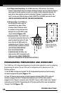
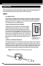
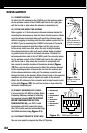
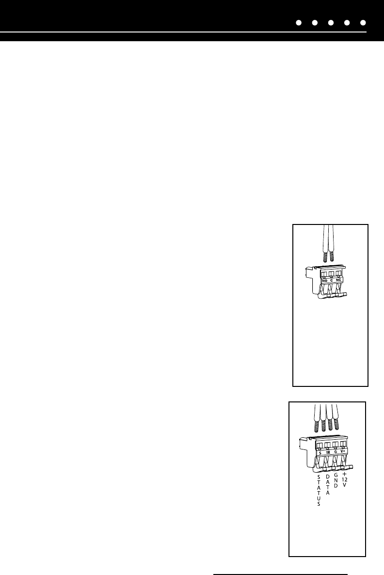
Figure 18.
HT-MSU sensor
removable
connection plug
N
O
R
M
A
L
L
Y
O
P
E
N
C
O
M
M
O
N
N
O
R
M
A
L
L
Y
C
L
O
S
E
D
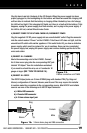
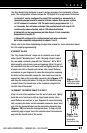
Figure 17.
Relay removable
connection plug
NILES AUDIO CORPORATION – 1-800-BUY-HIFI – 305-238-4373
21
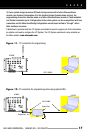
The Niles QuickConfig Software is used to assign (program) the functionality of these
jacks. The configuration software allows the 12V output to be programmed as follows:
a) Output #1 can be configured to output 12V constantly or momentarily. A
momentary output would be used to activate a device that requires a pulse
of 12V instead of a constant 12V. The pulse can be programmed for 1, 3
or 5 seconds, then off when activated. The constant mode will output 12V
continuously when activated, and no 12V when deactivated.
b) Output #2 can be programmed just like Output #1, but completely
independent of output #1.
c) Output #3 configured for constant output only when activated,
but is also completely independent of outputs 1 and 2.
Please refer to the Niles QuickConfig Configuration manual for more information about
the 12V output programmability.
9) CONNECT RELAYS
The “Dry Contact Closure” relays use 2-conductor wire to pair
either the NO “Normally Open” or NC “Normally Closed” side of
the removable connector plug with the “Common”. NO or NC is
determined by which device you are triggering. Strip 1/4 inch of
the insulation from the end of each wire, and tightly twist the end
of each wire until no frayed ends remain. Use a small flathead
screwdriver or your fingernail to raise the locking tabs, exposing
the holes on the removable connector. Insert each wire into the
appropriate hole on the removable connector plug (Figure 17)
and snap the locking tab down. To help you, the connector plug
is keyed. Insert the smooth side of the connector plug into the
smooth side of the socket.
10) CONNECT THE SENSOR CABLE TO IR INPUT
Strip 1/4 inch of the insulation from the end of each wire. Tightly
twist the end of each wire until no frayed ends remain. Use a
small flathead screwdriver or your fingernail to raise the locking
tabs, exposing the holes on the removable connector. Insert each
wire into the appropriate hole on the removable connector plug
(Figure 18) and snap the locking tab down. To help you, the
connector plug is keyed. Insert the smooth side of the connector
plug into the smooth side of the socket.